Do you have a question about the Toshiba RAS-107SAV-E6 and is the answer not in the manual?
Covers general safety instructions, cautions, and dangers for handling the air conditioner.
Details warnings and cautions specific to the installation process, including refrigerant handling.
Provides detailed specifications for indoor and outdoor units, including dimensions and capacities.
Presents operational data and characteristic curves for cooling and heating performance.
Key safety measures for handling R410A refrigerant during installation and servicing.
Guidance on selecting and installing piping materials and joints for R410A systems.
Lists tools exclusive and general tools required for R410A refrigerant handling and installation.
Procedure for recharging refrigerant, including important precautions and steps.
Details on brazing materials, flux, and procedures, including oxidation prevention.
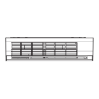
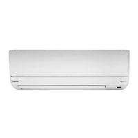
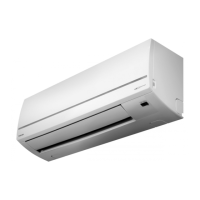
Diagrams illustrating the physical components and dimensions of the indoor unit.
Diagrams showing the external structure and key components of the outdoor unit.
Detailed wiring diagram for the air conditioner system, showing connections for all components.
List of electrical components for the indoor unit with their specifications.
List of electrical components for the outdoor unit with their specifications.
Diagram illustrating the refrigerant flow and major components in the air conditioning cycle.
Table summarizing operating data, including temperatures, pressures, and compressor speed.
Block diagram showing the control system and functions of the indoor unit.
Block diagram detailing the control functions and components of the outdoor unit.
Explanation of the overall control structure, roles of indoor/outdoor controllers, and communication signals.
Description of basic operation, including cooling, heating, AUTO, and DRY modes.
Details on indoor and outdoor fan motor control, capacity control, and current release.
Covers protective controls, defrost, ECO, temporary operation, and Hi-POWER modes.
Explanation of remote controller parts, operation, and display indications.
Illustrates installation steps, optional parts, accessories, and tools needed.
Guidance on selecting the installation place, cutting holes, and electrical work for the indoor unit.
Instructions for outdoor unit placement, precautions for weather, and refrigerant piping.
Details on refrigerant piping, evacuation, wiring, and drain hose installation.
Safety precautions for handling high voltage and preliminary checks for troubleshooting.
Interpreting indoor unit LED codes for self-diagnosis and identifying protective operations.
Using the remote controller's service mode to perform self-diagnosis and check fault codes.
Guidance for diagnosing common issues like no power, fan issues, and remote control problems.
Procedures for checking main parts like coils, sensors, and valves for proper function.
Step-by-step guide for replacing indoor unit components like the front panel and electric parts box.
Procedures for replacing major components in the outdoor unit, including the compressor and inverter.
Detailed exploded views and part numbers for the indoor unit components.
Detailed exploded views and part numbers for the outdoor unit components.
| Cooling Capacity | 2.5 kW |
|---|---|
| Heating Capacity | 3.2 kW |
| Refrigerant | R410A |
| Indoor Unit Dimensions (W x H x D) | 798 x 293 x 230 mm |
| Outdoor Unit Dimensions (W x H x D) | 660 x 530 x 240 mm |
| Power Supply | 220-240V, 50Hz |
| Indoor Unit Weight | 9 kg |
| Type | Split |
| Noise Level (Outdoor Unit) | 50 dB(A) |