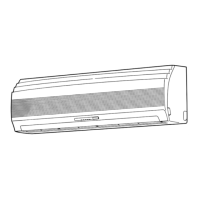
Do you have a question about the Toshiba RAS-10UKPX and is the answer not in the manual?
Electrical schematic illustrating the connections for specific indoor and outdoor unit models.
Electrical schematic for specific indoor/outdoor units, showing component connections.
Electrical schematics covering various model combinations, detailing internal connections.
Mechanism to prevent excessive refrigerating cycle pressure by controlling indoor heat exchanger temp.
Critical safety warnings and precautions for personnel during installation.
Instructions for connecting power supply and wiring for the indoor unit.
Detailed steps for connecting the power cord to the indoor unit.
Detailed procedures for connecting refrigerant pipes, including flaring and torque.
Steps to remove air and moisture from the refrigerant lines using a vacuum pump.
Instructions for connecting the connecting cable to the outdoor unit's terminal block.
Methods for checking refrigerant gas leaks at connection points.
General steps to follow when diagnosing issues with the air conditioner.
Initial checks to perform before detailed troubleshooting.
Methods for initial diagnosis based on unit symptoms and indicator lights.
Interpreting indicator lamp patterns for self-diagnosis of unit failures.
Using the remote control to access and interpret unit self-diagnosis codes.
Visual guides to diagnose and resolve specific operational problems.
Flowchart for diagnosing issues when the unit does not turn on or operate.
Flowchart for issues arising after replacing the indoor P.C. board.
Flowchart to diagnose why the outdoor unit fails to operate.
Flowchart for diagnosing issues when only the compressor fails to operate.
Flowchart for diagnosing issues when only the outdoor fan fails to operate.
Flowchart for diagnosing 4-way valve issues specifically during heating.
Flowchart for diagnosing issues when only the indoor fan fails to operate.
Diagnosing problems related to the remote control and indoor P.C. board.
Procedures and precautions for inspecting the unit's P.C. board.
| Brand | Toshiba |
|---|---|
| Model | RAS-10UKPX |
| Category | Air Conditioner |
| Language | English |


