Do you have a question about the Toshiba RAS-107SAV-E and is the answer not in the manual?
Covers general warnings, cautions, and dangers related to unit operation and maintenance.
Specific safety precautions for handling R410A refrigerant during installation and servicing.
Details cooling/heating capacity, power supply, dimensions, and weight for indoor/outdoor units.
Operation characteristic curves and capacity variation ratios based on temperature.
Precautions for safe installation and servicing with R410A refrigerant.
Details on piping materials, joints, and processing for R410A systems.
Lists specialized tools necessary for R410A refrigerant handling and installation.
Step-by-step guide for recharging refrigerant and safety notes.
Information on brazing filler materials, flux, and brazing methods.
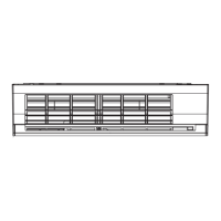
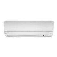
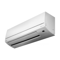
Diagrams and dimensions of the indoor unit's internal and external parts.
Diagrams and dimensions of the outdoor unit's external parts.
Detailed electrical schematic for the indoor unit's components.
Detailed electrical schematic for the outdoor unit's components.
List and specifications of electrical components used in the indoor unit.
List and specifications of electrical components used in the outdoor unit.
Visual representation of the refrigerant path and key components.
Key operating parameters for cooling and heating modes.
Shows MCU functions, signal flow, and component interactions for the indoor unit.
Shows inverter assembly, MCU functions, and signal flow for the outdoor unit.
Explains the roles of indoor and outdoor controllers and their communication.
Details on Cooling, Heating, AUTO, DRY, ECO, and other operational modes.
Procedure for setting and cancelling the auto restart function.
Guide to using remote control functions and understanding display icons.
Visual guides for indoor and outdoor unit placement and clearances.
Lists necessary accessories, optional parts, and installation tools.
Detailed steps for mounting, wiring, and piping the indoor unit.
Detailed steps for mounting, piping, and connecting the outdoor unit.
Specific methods for pipe shaping, connection, and system evacuation.
Identifies conditions that may appear as faults but are normal operation.
Initial troubleshooting steps including LED checks and self-diagnosis.
Interprets indoor unit LED flash codes for fault diagnosis.
Guide to using the remote controller's service mode for fault code retrieval.
Flowcharts for diagnosing specific operational issues like no power or fan failure.
Methods for testing key components such as sensors, motors, and PCBs.
Procedure to cancel or disable the automatic clean operation function.
Step-by-step instructions for disassembling and replacing indoor unit components.
Step-by-step instructions for disassembling and replacing outdoor unit components.
Exploded views and part numbers for the indoor unit's components.
Exploded views and part numbers for the outdoor unit's components.
Diagram showing component locations on the printed circuit board.
| Brand | Toshiba |
|---|---|
| Model | RAS-107SAV-E |
| Category | Air Conditioner |
| Language | English |