Do you have a question about the Toshiba RAS-107SAV-E3 and is the answer not in the manual?
Covers precautions for general use, installation, and electrical safety.
Details safety for new refrigerant, pressure, and contamination risks.
Includes warnings about modifications, weight, leaks, and grounding.
Lists cooling/heating capacity, power, noise, and dimensions for indoor/outdoor units.
Shows operational characteristics and capacity variation based on temperature.
Covers safety during installation, servicing, and handling of R410A refrigerant.
Details piping materials, processing, flare connections, and brazing techniques.
Lists tools exclusive for R410A and general tools for installation and servicing.
Provides steps for recharging refrigerant and evacuating the system.
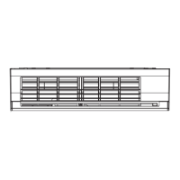
Illustrates the internal and external components of the indoor unit with dimensions.
Shows the external structure and dimensions of the outdoor unit.
Depicts the electrical connections for the indoor unit.
Illustrates the electrical connections for the outdoor unit.
Lists the specifications for various electrical parts in the indoor unit.
Details the specifications of electrical parts used in the outdoor unit.
Illustrates the refrigerant circuit and key components for cooling and heating.
Provides operating data for cooling and heating under specific conditions.
Shows the MCU functions and signal flow for the indoor unit control system.
Outlines the micro-computer block diagram for the outdoor unit's inverter assembly.
Describes the overall control system and roles of indoor/outdoor controllers.
Explains basic operation, cooling, heating, AUTO, DRY, ECO, and temporary modes.
Details fan motor, louver, capacity, and protective controls.
Covers defrost control, self-cleaning, comfort sleep, and Hi-POWER modes.
Provides instructions for enabling, disabling, and managing the auto restart feature.
Explains remote functions, operations, and display indicators.
Shows placement and mounting of indoor/outdoor units with dimensions.
Lists necessary accessories, optional parts, and tools for installation.
Details indoor unit placement, drilling, electrical work, wiring, and piping.
Covers outdoor unit placement, piping, wiring, gas leak tests, and evacuation.
Covers non-trouble conditions, primary judgment, and LED flashing codes.
Explains remote control self-diagnosis, wiring failure, and symptom-based troubleshooting.
Details methods for checking key components like PC boards, sensors, and motors.
Step-by-step guide for replacing indoor unit parts like panels, motors, and heat exchangers.
Instructions for replacing outdoor unit parts including cabinets, fans, compressors, and reactors.
Provides exploded views and part numbers for the indoor unit assembly.
Lists parts with exploded views for the outdoor unit assembly.
Shows the layout and identification of components on the PC board.
| Brand | Toshiba |
|---|---|
| Model | RAS-107SAV-E3 |
| Category | Air Conditioner |
| Language | English |