Do you have a question about the Toshiba RAS-107SKV-E6 and is the answer not in the manual?
Safety precautions for R410A installation/servicing, including pressure, tools, and leak checks.
Prioritize electrical safety, disconnect power, handle high voltage circuits with extreme care.
Ensure unit stability, check for refrigerant leaks, handle parts carefully, secure against seismic activity.
Low-temperature heating may require an antifreeze heater for drainage.
Details electrical properties, operating currents, power consumption, COP, and noise levels for indoor/outdoor units.
Provides dimensions for indoor/outdoor units, compressor details, and refrigerant piping specifications.
Safety precautions for R410A installation/servicing, including pressure, tools, and leak checks.
Specifies copper pipe types, flare/socket joints, and processing procedures for R410A piping.
Tools exclusively for R410A, detailing their specifications and interchangeability with R22.
General tools that can be used for R410A and R22 systems, including installation and measurement tools.
Detailed steps for recovering refrigerant, evacuating, and charging liquid refrigerant into the system.
Diagram showing the configuration of refrigerant cylinder, gauge manifold, and vacuum pump for charging.
Describes silver, phosphor bronze, and low-temperature brazing fillers, and the importance of flux.
Explains flux characteristics like activation temperature and types: noncorrosive and activated flux.
Specifies compatible piping materials, brazing fillers, and flux types for different joint types.
Describes using dry nitrogen gas flow during brazing to prevent oxidation in the pipe interior.
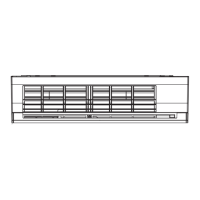
Exploded view and dimensions of the indoor unit, including air filter, heat exchanger, and mounting points.
Details mounting plate, drain hose, and refrigerant pipe connection points for indoor unit installation.
Exploded view and dimensions of the outdoor unit, including fan, compressor, and air inlets/outlets.
Detailed wiring diagram for the indoor unit, including sensors, motors, and control board connections.
Wiring diagram for the outdoor unit, illustrating connections for compressor, fan, and valves.
Specifications for indoor unit electrical components like fan motor, sensors, and louver motor.
Specifications for outdoor unit electrical parts including reactor, fan motor, sensors, and compressor.
Diagram showing refrigerant flow for cooling and heating operations for specific indoor/outdoor models.
Notes on allowable pipe length, height difference, and refrigerant amount for system operation.
Operating data for cooling mode, including pressures, temperatures, and compressor speeds by model.
Operating data for heating mode, including pressures, temperatures, and compressor speeds by model.
Block diagram illustrating indoor unit control logic, including sensor inputs, MCU functions, and outputs.
Shows remote control functions like mode selection, temperature setting, and fan speed control.
Block diagram detailing outdoor unit control, including sensors, inverter, and valve control logic.
Overview of control system, indoor/outdoor unit roles, and their primary functions.
Describes serial signal communication for operation commands and status information between units.
Explains basic operation, cooling, heating, auto, and dry modes, including fan speed control.
Explains control of indoor/outdoor fan motors and capacity adjustment methods.
Details various controls like protective, defrost, louver, ECO, PMV, auto restart, and remote operations.
Diagram showing placement and connection points for indoor and outdoor units, including piping and drainage.
Steps for loading batteries into the wireless remote controller before initial setup.
Details optional parts required for installation, such as refrigerant piping and insulating material.
Guidance on securing the outdoor unit against wind and attaching the drain nipple for defrost water.
Lists included accessories like installation plate, remote control, batteries, and manuals.
Details changes in tools for R410A, emphasizing differences from R22 and new requirements for installation.
Requirements for indoor unit placement, ensuring space, access, and avoiding sunlight/noise sources.
Guidelines for remote control placement, avoiding obstacles and interference for optimal signal reception.
Procedures for cutting holes for pipes and securely mounting the indoor unit's installation plate.
Instructions for electrical work, ensuring correct voltage, dedicated power source, and safe wiring practices.
Step-by-step guide for connecting the electrical cable to the indoor unit's terminal block and securing it.
Instructions for shaping refrigerant pipes and installing the drain hose, ensuring proper insulation and slope.
Instructions for fixing the drain cap and connecting pipes for left-hand and bottom-left piping configurations.
Procedures for securely attaching the indoor unit to the installation plate, including checking for firmness.
Guidelines for setting up the drainage system, ensuring proper slope and preventing dew-dropping.
Requirements for outdoor unit placement, considering space, noise, wind, and gas exposure.
Precautions for installing in snowy or cold regions, including snow protection and drain management.
Instructions for cutting and flaring copper pipes for refrigerant connections, including dimensions and tools.
Steps for connecting flare nuts, including tightening torque specifications and precautions.
Procedure for using a vacuum pump to evacuate refrigerant lines, ensuring proper pressure and time.
Precautions for opening and tightening packed valve stems, and handling valve caps with specified torque.
Steps for connecting the power cord and connecting cable to the outdoor unit terminals, preventing water ingress.
Method for performing a gas leak test using a leak detector or soap water on flare nut connections.
Procedure for setting remote control to A or B to manage multiple indoor units in proximity.
Overview of troubleshooting steps, including confirmation, judgment, and symptom analysis.
Safety warnings regarding high voltage, uninsulated circuitry, and handling the inverter assembly.
Precautions for inspecting the outdoor unit controller, especially capacitor discharging to prevent electric shock.
Confirms normal operation of the power breaker, supply voltage, and proper cable connection.
Identifies normal microcomputer operations that might appear as faults, such as compressor restart delay.
Describes primary judgment methods: LED flashing, self-diagnosis via remote, and symptom analysis.
Interprets flashing patterns of indoor unit LEDs (OPERATION, TIMER, FILTER) to identify specific faults.
Instructions on entering service mode, navigating check codes, and interpreting diagnostic results.
Details alphanumeric check codes displayed on the remote controller for identifying specific faults.
Table mapping check codes to causes, status, flashing errors, and recommended actions for diagnosis and repair.
Guides through checking power supply, voltage, cable connections, and fuses for power-on failures.
Diagnoses issues like no operation, fan display errors, compressor speed anomalies, and AUTO mode changes.
Checks power supply to fan motor, motor rotation, fan speed, and signal output for diagnosis.
Checks for direct sunlight, fluorescent lights, transmission indicators, and battery life.
Tests operation with temporary settings, signal tone on radio, and verifies transmission indicator light.
Checks voltage between indoor/outdoor terminals and serial signal transmission for outdoor unit failure.
Analyzes phenomena like unit stopping after 10-20 mins, requiring power cycle, or stopping with alarms.
Guides on checking PMV coil connection, positioning, inverter connection, and sensor seating.
Steps to check gas amount, valve clogging, and condensation at PMV outlet for system health.
Flowchart for diagnosing inverter issues, including fuse check, capacitor voltage, fan rotation, and winding resistance.
Procedures for checking compressor winding resistance and grounding to diagnose motor or board issues.
Precautions for safely removing and handling the indoor unit's P.C. board, including power disconnection and connector care.
Procedures for inspecting the P.C. board for burning, discoloration, or component issues.
Step-by-step checks for P.C. board faults, including fuse, voltage, indicators, compressor, and fan motor signals.
Diagram showing the layout of the indoor unit's P.C. board, including connectors and voltage points.
Graph illustrating the resistance characteristics of temperature sensors (TA, TC, TO, TS, TE) versus temperature.
Resistance values for indoor unit sensors, remote, louvers, and fan motor for diagnostic testing.
Resistance values for outdoor unit compressor, fan motor, valve coils, and reactor for diagnostic testing.
Methods for checking electrolytic capacitors and converter modules, including continuity and charging characteristics.
Procedure for checking diodes using a tester, including resistance values for good products and troubleshooting.
Lists symptoms of outdoor fan motor failure and potential causes like mechanical lock or circuit failure.
Provides a simple test procedure to determine if the outdoor fan motor is functional by checking resistance and rotation.
Steps involving modifying the indoor PC board and using the reset button to cancel Clean Operation.
Emphasizes turning off power, test runs, avoiding flames, and handling live parts with care.
Procedure for removing the indoor unit's front panel, including opening grilles and filters.
Steps for removing front panel screws and hooks, and instructions for reassembling the front panel.
Procedure for removing and replacing the electric parts box, including disconnecting sensors and motors.
Procedure for removing the horizontal louver shafts and the louver assembly from the unit.
Instructions for removing the evaporator, including pipe holders, fixing screws, and separating the heat exchanger.
Procedure for removing the bearing base and its screws, and caution for reassembly.
Procedure for removing the fan motor, including loosening set screws, removing covers, and cutting motor leads.
Guidelines for installing the cross flow fan, including positioning and securing it with a set screw.
Procedure for replacing the microcomputer, involving power shutdown, panel removal, and base removal.
Steps for removing and reattaching the outdoor unit's upper cabinet and front cabinet.
Detailed procedure for removing and reattaching the outdoor unit's front cabinet panels and screws.
Procedure for replacing the inverter assembly, including safety precautions for high voltage and capacitor discharging.
Procedure for removing the fan motor, propeller fan, and associated connectors.
Detailed steps for compressor replacement, including refrigerant extraction, partition removal, and pipe disconnection.
Procedure for removing and replacing the reactor, involving screw removal.
Procedure for removing and attaching the fan guard, including precautions to prevent scratches.
Procedure for replacing the PMV coil, including rotation and positioning instructions.
Procedure for disconnecting connectors and replacing the control board assembly, including heat sink and P.C. board base.
Step-by-step guide for cutting, stripping, soldering, and securing replacement temperature sensors.
Lists common service parts for sensors, including springs, tubes, tape, and terminals.
Exploded view and list of parts for the indoor unit, identifying components by location and part number.
Comprehensive list of indoor unit components, including motors, fans, sensors, and panels with part numbers.
Exploded view and list of parts for outdoor units, identifying components by location and part number.
Comprehensive list of outdoor unit components for RAS-137SAV-E6, including fan, compressor, and valves with part numbers.
Exploded view and list of parts for Outdoor Unit (Part-E), identifying components by location and part number.
| Type | Split System |
|---|---|
| Cooling Capacity | 2.5 kW |
| Heating Capacity | 3.2 kW |
| Power Supply | 220-240V, 50Hz |
| Indoor Unit Weight | 9 kg |
| Noise Level (Indoor) | 24 dB |