Do you have a question about the Toshiba RAS-10JKVP-E and is the answer not in the manual?
Detailed technical specifications for indoor and outdoor units, including dimensions, power, performance, and accessories.
Safety precautions, handling guidelines, and proper installation procedures for R410A refrigerant.
Requirements for refrigerant piping installation, materials, tools, and processing for R410A systems.
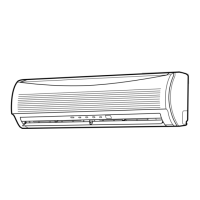
Diagrams and dimensions illustrating the internal and external structure of the indoor unit.
Diagrams and dimensions illustrating the internal and external structure of the outdoor unit.
Electrical wiring diagram for the indoor unit, including component connections and color identification.
Electrical wiring diagram for the outdoor unit, showing connections for compressor, fans, and power supply.
List of electrical components for the indoor unit with model names and specifications.
List of electrical components for the outdoor unit with model names and specifications.
Diagram illustrating the flow of refrigerant through the air conditioning system.
Tables detailing operational parameters under specific cooling and heating conditions.
Block diagram showing the internal control functions and connections of the indoor unit.
Block diagram illustrating the control logic and components of the outdoor unit inverter assembly.
Description of the air conditioner's control system, operation modes, and functional logic.
Details on temporary, auto restart, filter, remote control, Hi-POWER, ECO, and other operational features.
Essential safety warnings and guidelines for installing the air conditioner unit.
Step-by-step installation instructions, diagrams, parts, tools, and wiring for indoor and outdoor units.
Initial checks, LED codes, self-diagnosis, wiring failures, and common troubleshooting procedures.
Methods for diagnosing issues with the outdoor unit, inverter, P.C. boards, sensors, and motors.
Procedures for replacing main parts of the indoor unit, including front panel, dust collector, and microcomputer.
Procedures for disassembling and replacing major components of the outdoor unit.
Visual breakdown of indoor unit parts with associated list for identification.
| Cooling Capacity | 2.5 kW |
|---|---|
| Heating Capacity | 3.2 kW |
| Power Supply | 220-240V, 50Hz |
| Refrigerant | R410A |
| Weight (Indoor Unit) | 9 kg |
| Noise Level (Outdoor Unit) | 50 dB |