– 24 –
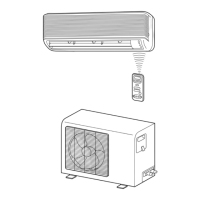
8-3. Installation
8-3-1. Optional Parts
<Drainage>
Part
code
A
B
C
Q’ty
Each
one
1
Each
one
Parts name
Refrigerant piping
Liquid side : ø6.35 mm
Gas side : ø9.52 mm
Pipe insulating material
(polyethylene foam, 6 mm thick)
Putty, PVC tapes
<Anchor bolt arrangement of outdoor unit>
Fig 8-3-1 Air outlet
• Secure the outdoor unit with the anchor bolts if the
unit is likely to be exposed to a strong wind.
• Use ø8 or ø10 anchor bolts.
• If it is necessary to drain the defrost water from
the outdoor unit, attach
12
drain nipple to the
bottom plate of the outdoor unit before installing it.
The drain nipple is located as shown above.
Fig 8-3-2
• Install the provided drain nipple in the hole of the
bottom plate of the outdoor unit. (See the above
figure.)
• Perform proper drainage processing using a drain
hose sold separately or one on the market. (Inner
diameter : 16 mm)
• Do not use an ordinary hose on the market,
because it tends to get flat and as a result, it
prevents water from draining.
600mm
Air inlet
111mm
Drain nipple
30mm
230mm
Air outlet
12
Drain hose sold
separately or one on the
market.
12
Drain nipple
Bottom plate
ø25
 Loading...