Do you have a question about the Toshiba RAS-10SAV-A and is the answer not in the manual?
| Brand | Toshiba |
|---|---|
| Model | RAS-10SAV-A |
| Category | Air Conditioner |
| Language | English |
Details operational curves for cooling and heating based on compressor speed, illustrating current draw versus speed.
Shows how cooling and heating capacity vary with outside temperature, presented in graphical format.
Crucial safety precautions for handling R410A refrigerant during installation and servicing, emphasizing pressure and impurity risks.
Covers materials, joints, and processing techniques for refrigerant piping with R410A, including pipe dimensions and flare processing.
Lists and categorizes tools required for R410A systems, distinguishing between exclusive and general-purpose tools.
Details the step-by-step procedure for recharging refrigerant, including system configuration and safety measures.
Explains materials, flux requirements, and methods for brazing pipes to prevent oxidation and ensure integrity.
Illustrates the dimensions and components of the indoor unit with detailed diagrams of its external and internal structure.
Provides dimensional views and component layouts for the outdoor unit, including installation dimensions and detail drawings.
Details the wiring diagram for the indoor unit, showing connections to terminal blocks, PCB, and various components.
Presents the wiring diagram for the outdoor unit, illustrating connections to the P.C. board, motors, and other components.
Lists electrical components used in the indoor unit with their types, model names, and specifications.
Details the electrical parts for the outdoor unit, including model names, ratings, and specifications for each component.
Illustrates the flow of refrigerant through the indoor and outdoor units, marking key components and measurement points.
Provides operational data under specific cooling and heating conditions, including temperatures, pressures, and speeds.
Shows the control logic and signal flow for the indoor unit's microcomputer, including sensor inputs and output controls.
Details the control system for the outdoor unit's inverter assembly and microcomputer, outlining PWM synthesis and protection functions.
Provides an overview of the air conditioner's capacity-variable type, AC motor usage, and control system.
Describes the functions of the indoor and outdoor unit controllers and their serial signal communication.
Details the contents of operation command signals exchanged between indoor and outdoor unit controllers.
Explains the basic operation control flow involving remote controller, indoor unit, and outdoor unit communication.
Describes the sequence of operations for cooling and heating modes, including signal transfer and unit control.
Explains the automatic operation mode selection based on room temperature and previous operation status.
Details the dehumidification mode, including room temperature detection and fan speed control.
Provides step-by-step instructions on how to enable the auto restart function using the RESET button.
Explains the procedure to disable the auto restart function, repeating the setting process.
Lists and describes the functions of each button and indicator on the remote controller.
Explains how to operate the remote control for various modes like ONE-TOUCH, AUTOMATIC, and COOL/HEAT/FAN ONLY.
Details the meaning of various symbols and indicators displayed on the remote controller's screen.
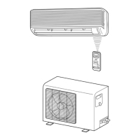
Illustrates installation layouts for indoor/outdoor units, optional parts, accessories, and necessary tools.
Covers indoor unit placement, hole cutting, mounting plates, electrical work, wiring, and piping connections.
Details outdoor unit placement, refrigerant piping connection, evacuation, wiring, and leak testing procedures.
Covers first confirmation, power checks, primary judgments, LED analysis, and basic troubleshooting steps.
Explains using the remote controller in service mode for self-diagnosis, check codes, and caution at servicing.
Provides diagnostic steps based on symptoms like no operation, fan issues, wiring failures, and specific check codes.
Details troubleshooting for inverter assembly and outdoor unit components using flowcharts and check procedures.
Outlines methods to check P.C. boards, sensors, motors, compressor resistance, and capacitors.
Describes procedures to judge the condition of the outdoor fan motor by checking rotation and winding resistance.
Details procedures for replacing indoor unit components: front panel, electrical parts, louvers, heat exchanger, fans, and base bearing.
Explains the procedure for removing and replacing the microcomputer (P.C. board) assembly from the unit.
Covers detachment and attachment of outdoor unit parts: cabinets, inverter assembly, control boards, motors, and sensors.
Provides an exploded view and parts list for indoor unit electronic components, including PC boards and sensors.
Shows an exploded view and parts list for the main mechanical assemblies of the indoor unit, like panels and fans.
Presents an exploded view and parts list for major outdoor unit assemblies and components like fan, compressor, and reactor.
Offers an exploded view and parts list for outdoor unit electronic components, including heatsinks and capacitors.