– 80 –
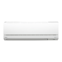
11-8-3. Indoor Unit (Other Parts)
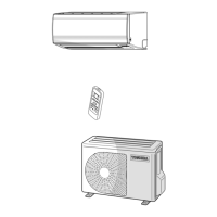
11-8-4. Outdoor Unit
No.
1
Part name
Room temp. (TA) sensor
Heat exchanger (TC) sensor
Checking procedure
Disconnect the connector and measure the resistance value with tester.
(Normal temp.)
Temperature
Sensor
TA, TC (kΩ)
10°C20°C25°C30°C40°C
20.7 12.6 10.0 7.9 4.5
5
4
3
2
1
White
Yellow
Yellow
Yellow
Yellow
5
4
3
2
1
Refer to 11-5-1. (5).
Measure the resistance value of each winding coil by using the tester.
(Under normal temp. 25°C)
Position
1 to 2
1 to 3
1 to 4
1 to 5
Resistance value
250Ω ± 7%
Refer to 11-5-1. (3) and (4).
2
3
Remote controller
Louver motor
24BYJ48-HTP
4 Indoor fan motor
FILE NO. SVM-13092
1 Compressor
(Model : ASM89D16UEZ)
No. Part name Checking procedure
White Red
Back
Position Resistance value
Red - White
White - Black 1.44Ω (20°C)
Black - Red
Measure the resistance value of each winding by using the tester.
Under 20°C
Measure the resistance value of winding by using the tester.
Red
White Blac
Measure the resistance value of winding by using the tester.
Resistance value
2210 ± 221Ω
Under 20°C
Measure the resistance value of winding by using the tester.
COM
COM
254
Y
W
GR BL
1
GR
6
O
3
Position
Gray - White
Gray - Orange
Gray- Yellow
Gray- Blue
Resistance value
42 to 50Ω
42 to 50Ω
42 to 50Ω
42 to 50Ω
Under 20°C
Position
Red - White
White - Black
Black- Red
Resistance value
20 to 22Ω
20 to 22Ω
20 to 22Ω
2
3
4
Outdoor fan motor
(Model : ICF-140-43-4R)
4-way valve coil
(Model : SQ-A2522G-000352)
Pulse modulating valve coil
 Loading...