Do you have a question about the Toshiba RAS-13N3KVR-E and is the answer not in the manual?
Detailed specifications and performance curves for the 10K model.
Detailed specifications and performance curves for the 13K model.
Safety precautions for handling R410A refrigerant during installation.
Guidelines and materials for refrigerant piping installation.
Required and general tools for R410A refrigerant systems.
Procedure for recharging refrigerant into the system.
Methods, materials, and flux for pipe brazing.
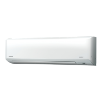
Exploded view and dimensions of the indoor unit.
Exploded view and dimensions of the outdoor unit.
List and specifications of electrical parts for the indoor unit.
List and specifications of electrical parts for the outdoor unit.
Detailed diagram of the refrigerant cycle.
Performance data measured under specific operating conditions.
Control logic and signal flow for the indoor unit.
Control logic and signal flow for the outdoor unit.
Overview of the air conditioner's control system architecture.
Detailed explanation of basic and specific operation modes.
How to set and use the auto restart feature.
Explanation of remote controller buttons and display indicators.
Visual guide for unit placement and connection points.
Lists optional parts, accessories, and servicing tools.
Instructions for installing the indoor unit, including placement and wiring.
Instructions for installing the outdoor unit, including placement and piping.
Final checks like gas leak test and remote control setup.
Initial checks for power supply and voltage.
Basic methods for diagnosing unit problems.
Interpreting error codes from indoor unit LED indicators.
Using the remote controller for detailed self-diagnosis.
Troubleshooting guide based on specific operational symptoms.
Troubleshooting procedures for specific error codes.
Steps to check and diagnose air purifier and ionizer issues.
Systematic troubleshooting for the outdoor unit and inverter.
Procedures for checking the functionality of major components.
How to check the outdoor fan motor.
Procedures for replacing parts within the indoor unit.
Procedures for replacing parts within the outdoor unit.
Detailed parts breakdown for the indoor unit.
Exploded view of the indoor unit's electronic components.
Detailed parts breakdown for the outdoor unit.
Diagram showing the layout of components on the PC board.
| Brand | Toshiba |
|---|---|
| Model | RAS-13N3KVR-E |
| Category | Air Conditioner |
| Language | English |