Do you have a question about the Toshiba RAS-18S2AH-ES and is the answer not in the manual?
Detailed diagrams and dimensions of the indoor unit components.
Detailed diagrams and dimensions of the outdoor unit components.
Wiring schematic for specific air conditioner models.
Wiring schematic for other air conditioner models.
Electrical component specifications for indoor units.
Electrical component specifications for outdoor unit.
Electrical component specifications for outdoor unit.
Electrical component specifications for indoor units.
Electrical component specifications for outdoor unit.
Electrical component specifications for outdoor unit.
Refrigeration cycle diagram for specific models.
Refrigeration cycle diagram for specific models.
Refrigeration cycle diagram for specific models.
Refrigeration cycle diagram for specific models.
Control block diagram for specific models.
Control block diagram for other specific models.
Details on remote control functions and buttons.
Explanation of remote control display indicators.
General overview of air conditioner control system.
Explanation of different operation modes.
Overview of safety and reliability functions.
Details on one-touch comfort operation.
Details on Hi POWER operation.
Details on QUIET operation.
Details on ECO operation.
Details on COMFORT SLEEP operation.
Information about the filter check indicator.
Functionality and setup of auto restart.
Details on self-cleaning operation.
Important safety precautions for installation.
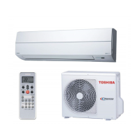
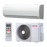
Visual guide for installing indoor and outdoor units.
General installation steps and parts.
Tools required for installation and servicing.
Procedures for installing the indoor unit.
Procedures for installing the outdoor unit.
Procedures for performing test operation after installation.
General steps for troubleshooting.
Fundamental checks before troubleshooting.
Initial diagnosis based on symptoms.
Using the remote control for self-diagnosis.
Flowcharts for diagnosing faulty components.
Specific troubleshooting steps for the indoor unit.
Troubleshooting wiring issues between units.
Steps to check and troubleshoot the P.C. board.
Steps to troubleshoot the remote control.
Procedures for replacing parts in the indoor unit.
Procedures for replacing parts in the outdoor unit.
Exploded view and parts list for indoor unit assembly.
Exploded view and parts list for indoor unit components.
Exploded view and parts list for outdoor unit.
Exploded view and parts list for outdoor unit.
| Type | Split System |
|---|---|
| Cooling Capacity | 5.0 kW |
| Heating Capacity | 5.6 kW |
| Refrigerant | R410A |
| Power Supply | 220-240V, 50Hz |
| Energy Efficiency Ratio (EER) | 3.21 |
| Coefficient of Performance (COP) | 3.61 |
| Outdoor Unit Dimensions (W x H x D) | 780 x 290 x 290 mm |
| Noise Level (Outdoor) | 50 dB(A) |