Do you have a question about the Toshiba RAS-22SAV-E and is the answer not in the manual?
| Brand | Toshiba |
|---|---|
| Model | RAS-22SAV-E |
| Category | Air Conditioner |
| Language | English |
Safety guidelines for general users regarding power supply cord.
Important warnings related to new refrigerant installation and power supply.
Critical warnings about high voltage, electrical shock, and proper grounding.
General warnings for safe operation, installation, and electrical work.
Graphs showing operational characteristics vs. compressor speed.
Graphs illustrating capacity changes based on outdoor temperature.
Safety precautions for handling R410A during installation and servicing.
Guidelines for installing refrigerant piping with R410A.
Details on copper pipes and joint types for R410A.
Procedures for processing piping materials, including flare processing.
Lists tools required for R410A installation and general tools.
Step-by-step guide for recharging refrigerant.
Information on brazing pipe materials and flux usage.
Procedure for brazing, focusing on preventing oxidation.
Exploded view and dimensions of the indoor unit.
Exploded view and dimensions of the indoor unit.
Exploded view and dimensions of the outdoor unit.
Tables showing operational data for cooling and heating modes.
Block diagram showing the control logic of the indoor unit.
Block diagram detailing the outdoor unit's control system.
Overview of the air conditioner's control system functions.
Detailed description of various operational modes and functions.
Control flow and applicable data for basic operation.
Control flow for cooling and heating modes.
Control flow for automatic operation mode.
Control flow for dry operation mode.
Details on indoor fan motor speed control in cooling operation.
Control methods for the outdoor fan motor speed.
How capacity is adjusted based on load via compressor revolution.
Function to prevent inverter damage by controlling current.
Protective control for indoor heat exchanger temperature.
Control logic for defrost operation in heating mode.
Explanation of the energy-saving ECO operation mode.
How to perform temporary AUTO or COOL operation.
Functionality of the air purification system.
Control mechanism of the Pulse Modulating Valve.
How the self-cleaning function operates after cooling/dry cycles.
Setting the remote control for multi-unit installations.
Operation of the quiet mode for reduced noise.
Function for energy saving and comfort during sleep.
Purpose and setting of the short timer.
Fully automated operation tailored to user preferences.
Operation mode for faster cooling or heating.
Indicator for filter cleaning notification.
Functionality for automatic restart after power failure.
Procedure to disable the auto restart function.
Identification and operation of remote controller functions.
Details on dry operation for dehumidification.
Operation of the air purifier and ionizer.
How to activate Hi-POWER mode.
How to activate ECO mode for energy saving.
Performing operation without the remote control.
Setting ON and OFF timers for operation.
Setting preferred operations for future use.
Setting the auto restart function after power failure.
How to activate quiet operation for reduced noise.
Activating comfort sleep mode for energy saving.
Setting the sleep timer.
Explains the display symbols and indicators on the remote controller.
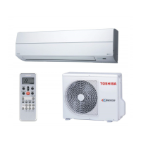
Diagram showing the placement of indoor and outdoor units.
Lists optional parts, accessories, and tools for installation.
Details new tools required for R410A and changes in components.
Guidelines for installing the indoor unit.
Recommended locations for indoor unit installation.
Procedures for drilling holes and mounting the installation plate.
Instructions for electrical connections and power supply.
Steps for connecting the indoor unit's wiring.
How to install piping and the drain hose for the indoor unit.
Final steps for mounting and securing the indoor unit.
Procedures for ensuring proper drainage of the indoor unit.
Guidelines for installing the outdoor unit.
Recommended locations for outdoor unit installation.
How to install water-proof caps and drain nipple for outdoor unit.
Instructions for connecting refrigerant pipes, including flaring.
Procedure for evacuating air from the system using a vacuum pump.
Steps for connecting power and connecting cables to the outdoor unit.
Procedures for testing the system after installation.
How to check for gas leaks after installation.
Steps to perform a system test operation.
How to set the auto restart function.
Setting the remote controller for multi-unit installations.
Safety warnings for working with the new inverter.
Safety measures for inspecting the outdoor unit's control section.
Initial checks for power supply, voltage, and normal operation.
Methods for initial troubleshooting.
Diagnosing issues using indoor unit LED indicators.
Using the remote controller for self-diagnosis and check codes.
Steps to enter service mode for diagnosis.
Important cautions to follow during servicing.
Troubleshooting based on specific symptoms.
Troubleshooting steps for the indoor unit and remote controller.
Troubleshooting steps if the indoor fan motor fails to operate.
Troubleshooting fan motor auto-rotation upon power-on.
Diagnostic steps for remote controller issues.
Diagnosing problems related to wiring failures.
Troubleshooting specific error codes related to sensors and gas leakage.
General troubleshooting guide.
Steps to check the functionality of the air purifier.
Checking the operation of the minus ion generator.
Diagnostic procedures for the outdoor unit.
Overview of inverter assembly diagnosis.
Simple checks for major components.
Procedures for checking the indoor unit's P.C. board.
Layout diagram of the indoor unit's P.C. board.
Checking procedures for other indoor unit parts.
Checking procedures for outdoor unit components.
Detailed checking methods for capacitors and diode blocks.
Simple method to determine if the outdoor fan motor is functional.
Procedures for replacing main parts of the indoor unit.
Procedure for replacing the microcomputer.
Procedures for detaching and attaching the outdoor unit.
Exploded view and parts list for the indoor unit.
Exploded view and parts list for the outdoor unit.
Layout diagram of the outdoor unit's P.C. board.