– 25 –
FILE NO. SVM-01010
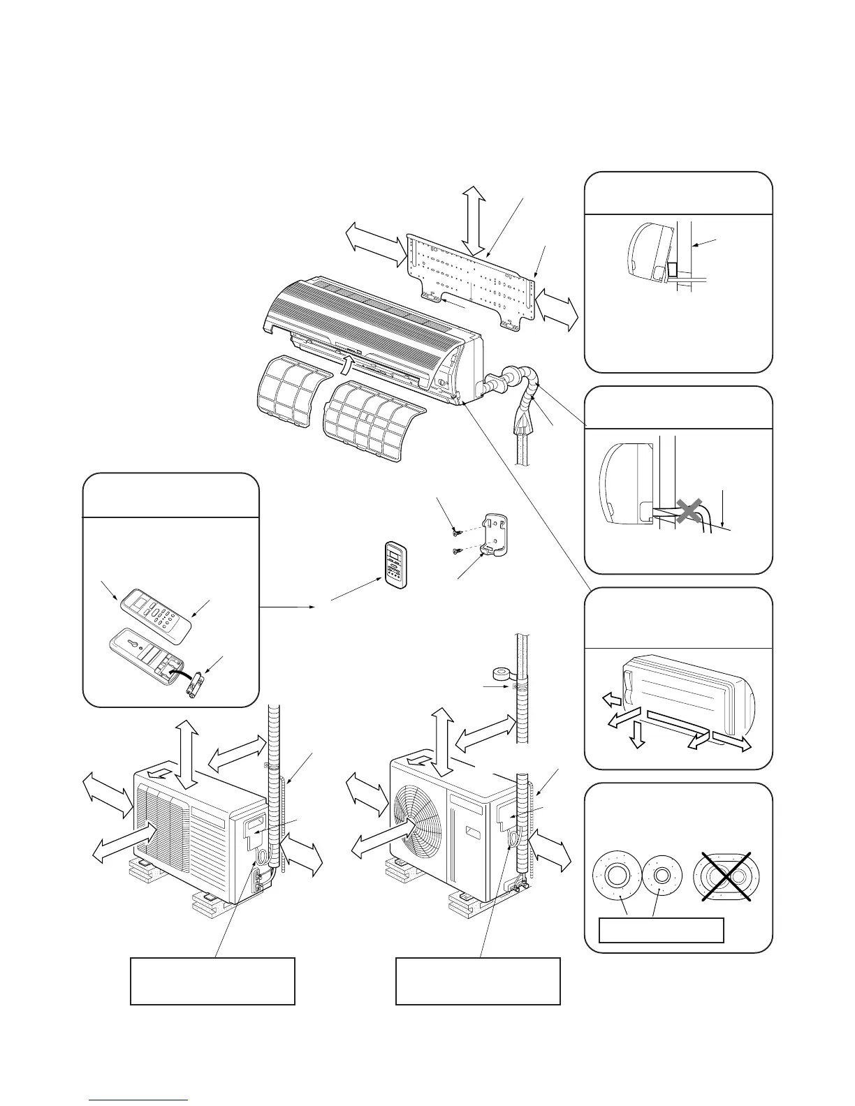
8-2. Installation Diagram of Indoor and Outdoor Units
For installation of the indoor unit, use the paper pattern on the back of the installation manual.
Air filter
Vinyl tape
Apply after carrying
out a drainage test.
Saddle
1 Installation
plate
Hook
Hook
Before install the wireless
remote control
• With the remote control cover
open, load the batteries supplied
correctly, observing their
polarity.
2 Wireless remote control
3 Batteries
Cover
Extension drain hose
(Option:RB–821SW)
65 mm or more
170 mm
or more
170 mm or more
100 mm
or more
600 mm or more
100 mm or more
600 mm
or more
600 mm or more
600 mm or more
100 mm or more
600 mm
or more
100 mm or more
600 mm or more
24 Class
18 Class
Electric
parts cover
Extension drain hose
(Option:RB–821SW)
Shield
pipe
Do not allow the drain hose
to get slack.
Cut the piping hole
sloped slightly
Make sure to run the drain
hose sloped downward.
Electric
parts
cover
For the rear left and left
piping
Wall
Insert the cushion between
the indoor unit and wall,
and lift indoor unit to make
work easier.
The auxiliary piping can be
connected the left, rear left,
rear, right or bottom.
Left
Rear left
Right
Rear
Bottom
Insulate the refrigerant
pipes separately with
insulation, not together.
6 mm thick heat resisting
polyethylene foam
6 Pan head
wood screw
4 Remote control holder
2 Wireless remote
control
Loop the connective cable
(about 100 mm in diameter
and 300 – 350 mm long).
Loop the connective cable
(about 100 mm in diameter
and 300 – 350 mm long).
 Loading...