Base plate
Motor base
Separate plate
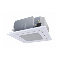
Air-outlet
cabinet
Inverter
assembly
Side cabinet
(right)
Base plate
Valve fixing plate
No. Part name Procedure Remarks
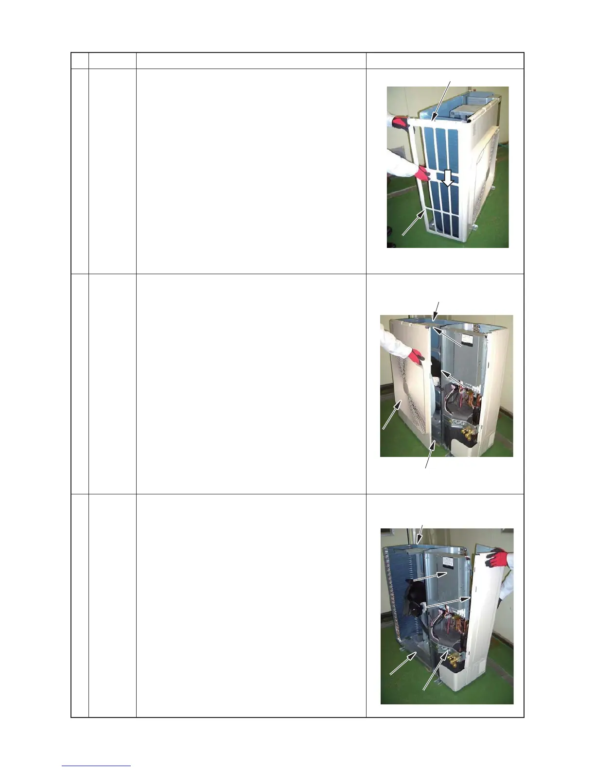
d
Side
cabinet
(left)
1. Detachment
1) Following to work of Detachment of c.
2) Remove the side cabinet (left) and base plate screws.
(2 pcs, Ø4 ×10 hexagon screws)
3) Slide the side cabinet (left) downwards and remove.
2. Attachment
Attach the side cabinet (left) in the reverse process of
“1. Detachment”.
e
Air-outlet
cabinet
1. Detachment
1) Following to work of Detachment of c and d.
2) Remove the screws from the Air-outlet cabinet and
separate plate. (3 pcs, Ø4 × 8)
3) Remove the screws from the Air-outlet cabinet and
base plate. (2 pcs, Ø4 × 10 hexagon screws)
4) Remove the screws from the Air-outlet cabinet and
motor base. (2 pcs, Ø4 × 8)
5) Remove the screws from the Air-outlet cabinet and
heat exchanger. (3 pcs, Ø4 × 8)
2. Attachment
Attach the Air-outlet cabinet in the reverse process of
“1. Detachment”.
f
Side
cabinet
(right)
1. Detachment
1) Following to work of Detachment of c.
2) Remove the screws securing the inverter assembly
and side cabinet (right). (2 pcs, Ø4 × 8)
3) Remove the screws form the side cabinet (right) and
valve fixing plate. (2 pcs, Ø4 × 8)
4) Remove the screws form the side cabinet (right) and
piping panel (rear). (2 pcs, Ø4 ×10 hexagon screws)
5) Remove the screws form the side cabinet (right) and
base plate. (1pcs, Ø4 ×10 hexagon screw)
6) Remove the screws from the side cabinet (right) and
heat exchanger. (3pcs, Ø4 × 10 hexagon screws)
2. Attachment
Attach the side cabinet (right) in the reverse process of
“1. Detachment”.