– 102 –
No. Part name Procedure Remarks
g
Electrical
part
(Control
P.C. board )
1. Detachment (Control P.C. board)
1) Following to work of Detachment of
c
.
WARNING
Do not disassemble the inverter for a minute after the
power is turned off since there is a risk of electric shock.
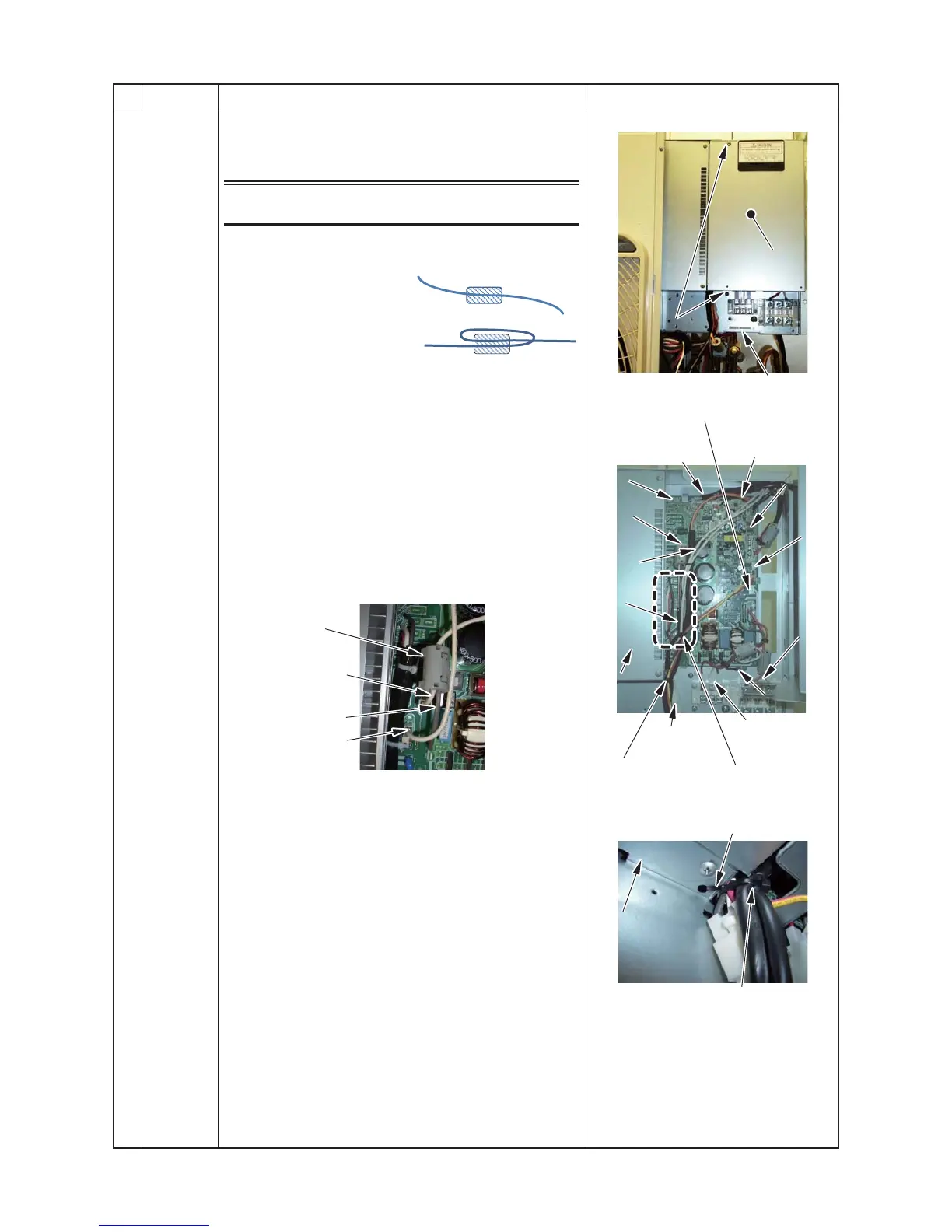
Inverter cover
Pressure
switch
LED indicator
board
Fan motor lead
Reactor
lead
Clamp filter
PMV coil
Duct cover
Earth wire
Supply wire
[Detail A]
Example 1
Example 2
[Detail.A]
Clamp filter
(Example 1)
Reactor lead B1
Board lead wire
Reactor lead B2
*1.Ensure to bundle again with a commercially available
code clamp
*2.Ensure to fix the clamp
filter where it was removed
when reassembling the
inverter.
2) Remove the inverter box and inverter cover fixing
screw (Upper side).
3) Loosen the inverter box and inverter cover fixing screw
(Lower side).
4) Cut the binding band A1 bundling the fan motor lead,
compressor case thermolead,4-way valve coil lead and
reactor lead. (one position)
5) Cut the binding band A2 bundling the compressor lead,
compressor case thermolead, 4-way valve coil lead
and fan motor. (one position)
6) Remove the clamp filter from the reactor lead A1 and
P.C. board lead.
7) Remove the reactor lead B1 and the reactor lead B2
from control P.C. board.
8) Cut the binding band A3 fixing compressor lead and
inverter box.
9) Remove the connector connecting to the control P.C.
board.
(Temperature sensor, PMV coil, 4-way valve coil,
Compressor case thermostat, Pressure switch, Fan
motor. LED indicator board)
10) Remove the connector of the compressor lead.
∗ Release the lock on the housing part to remove the
connector
11) Remove the earth wire connecting to the control
board.
(ST3T Ø4×8 :1 pcs)
12) Remove supply wire (Red (L), White (N)) or indoor
supply wire from each P.C. board
13) Remove the duct cover.
(ST3TØ4×8 2 pcs)
 Loading...