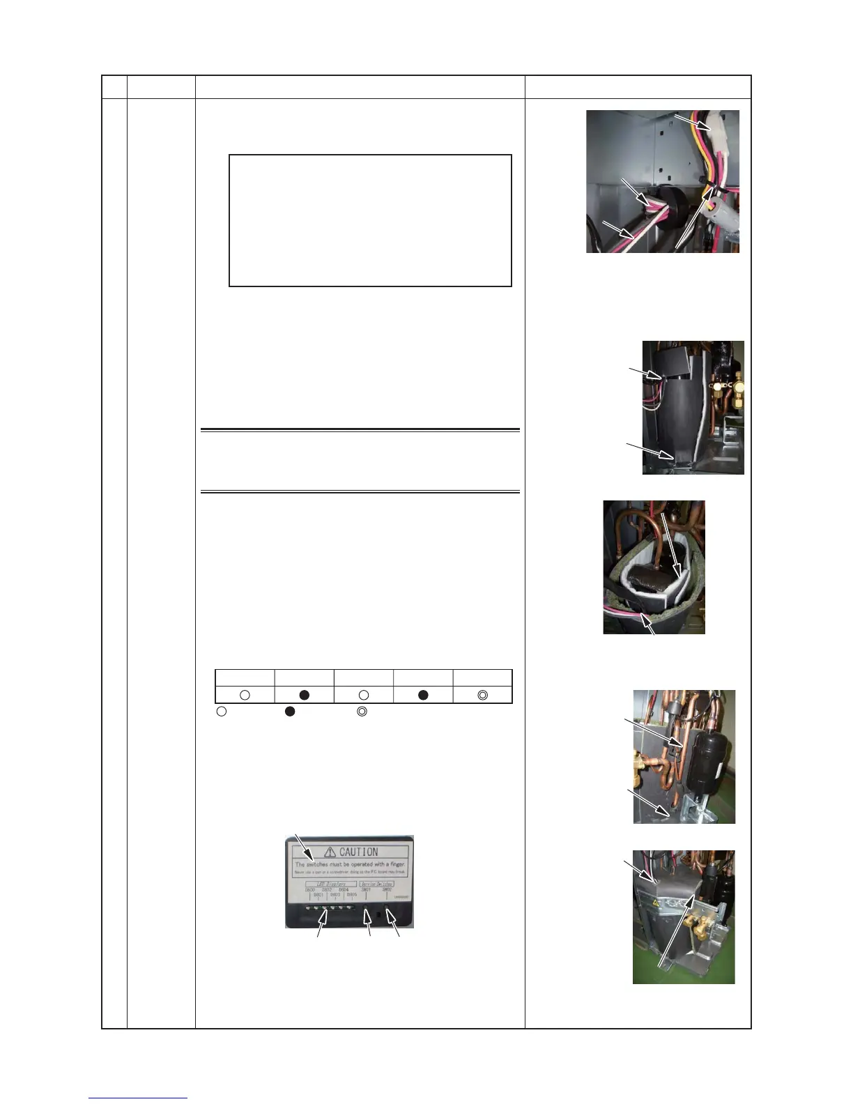
Compressor lead connector
Ferrite core
Roll the compressor lead
4 times on the ferrite core
Compressor lead
(Red • White • Black)
Bundle Four-way valve lead ,
TD sensor lead,
Compressor lead,
Compressor case thermo lead,
and Fan motor lead to fix them
into sheet metal hole on inverter
box by binding band.
Pull out the compressor lead
and compressor case thrmostat
lead from this gap.
Match the gap on the
soundproof board (inner)
to the compressor leg.
Wrap the seam of the soundproof (inner)
and soundproof (outer) about this position.
Match the gap on
sound proof board (outer)
to the suction pipe.
Pull out the compressor lead,
the compressor case thermo le
ad
from the gap of the soundproof
Push the sound proof plate (inner and upper)
into the inside of the soundproof (outer)
securely so that there is no clearance between
sound proof (upper) and sound proof (outer)
No. Part name Procedure Remarks
i
Compressor
and
compressor
lead
(continued)
2. Attachment
1) Attach the compressor in the reverse process of
“1. Detachment”.
D800
: Go ON, : Go OFF, : flash (5 times/sec.)
D801 D802 D803 D804
• Also ensure to replace the compressor lead
after replacing the compressor. (Compressor
lead replacement code: 43160654)
At this time please ensure to wind the
compressor lead 4 times around the ferrite core.
• Install the sound insulation board (inner and
outer) through the space between the
compressor and the piping, and between the
pipes and separate plate as shown on the right.
3. Vacuum
1) Connect the vacuum pump to the charge port of the
liquid and gas pipe valves and the check joint on the
high pressure side, and then operate the vacuum
pump.
2) Vacuum until the vacuum low pressure gauge reaches
1 (mmHg).
NOTE
Fully open the electronic control valve before the vacuum
process. If closed the vacuum pipe between the liquid pipe
valve and electronic control valve of the outdoor unit may
not be able to be drawn through.
Method for forcibly fully opening the electronic control valve
• Turn on the power supply breaker.
• Ensure that D805 of the LED indication of the outdoor is
lit up. If D805 is not lit up (off or flashing) then push and
hold down SW01 and SW02at the same time for at least
5 seconds and check that D805 lights up.
• Push and hold SW01 down for at least 5 seconds or to
confirm that D804 is slowly flashing (once/second).
• Push SW01 several times until the LED
indications(D800 to D804) become the following.
• Push SW02 and D805 will start rapidly flashing.
• Push and hold SW02 down for at least 5 seconds and
D804 will start slowly flashing.
Once D805 lights up the PMV will start to open.
After 30 seconds turn off the power breaker.
4. Refrigerant encapsulation
1) Add the amount of refrigerant determined by the pipe
length using the charge port of the valve.
LED indicator
D800~D805 SW01 SW02
 Loading...