– 108 –
No. Part name Procedure Remarks
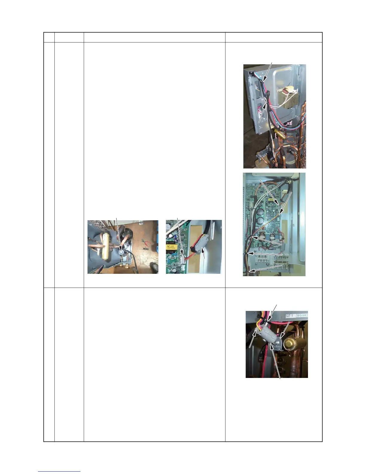
j
PMV coil
1. Detachment
1) Following to work of Detachment of
f
.
2) Cut the binding band (two positions) on the back
surface
3) Pull the connector for PMV coil out of control
P.C. board.
(Remove the clamp filter installed to near the
connector to attach it to the coil lead replaced.)
4) Remove the coil from the PMV body by rotating the coil
(about 45° while drawing the coil upward.
2. Attachment
Attach the PMV coil in the reverse process of
“1. Detachment”
1) Fix the coil positioning protrusions securely in the
concavities of the PMV body.
(Fix the coil in the direction where lead wire comes out
at the body’s left diagonally behind.)
2) Attach the connector on the PMV coil to the control
P.C. board.
(Attach the clamp filter installed to near the connector
one turn (2 time passes))
k
4-way
valve coil
1. Detachment
1) Following to work of Detachment of
g
, 1) to 5).
2) Cut the binding band A5 bundling up
4-way valve coil lead, TD sensor lead
Compressor lead, Compressor case thermo lead and
Fan motor lead.
3) Cut the binding band A6 fixing the clamp filter.
4) Remove the 4-way valve coil.
(M5 screw)
2. Attachment
Attach the 4-way valve coil in the reverse process of
“1 Detachment”.
∗1 Fix the 4-way coil with its lead wire upward.
∗2 Fix the clamp filter around the 4-way valve coil through
a commercially available binding band into the hole for
fixing binding band of clamp filter. (1 time pass)
Bundle the all lead wires on
the back face and then cut the
binding band fixing inverter box.
Cut the binding band
 Loading...