– 109 –
No. Part name Procedure Remarks
l
Fan guard
1. Detachment
1) Following to work of Detachment of
e
NOTE
Do the work on cardboard or a cloth etc. spread out to
prevent the product from being scratched.
2) Remove the outlet cabinet and place the fan guard
side facing down.
3) Remove the claws (8 places) of the fan guard.
2. Attachment
1) Hook the hooks from the front side and press the claws
(8 places) by hand to fix them in place.
NOTE
Ensure that all the claws are fixed in their specified
position.
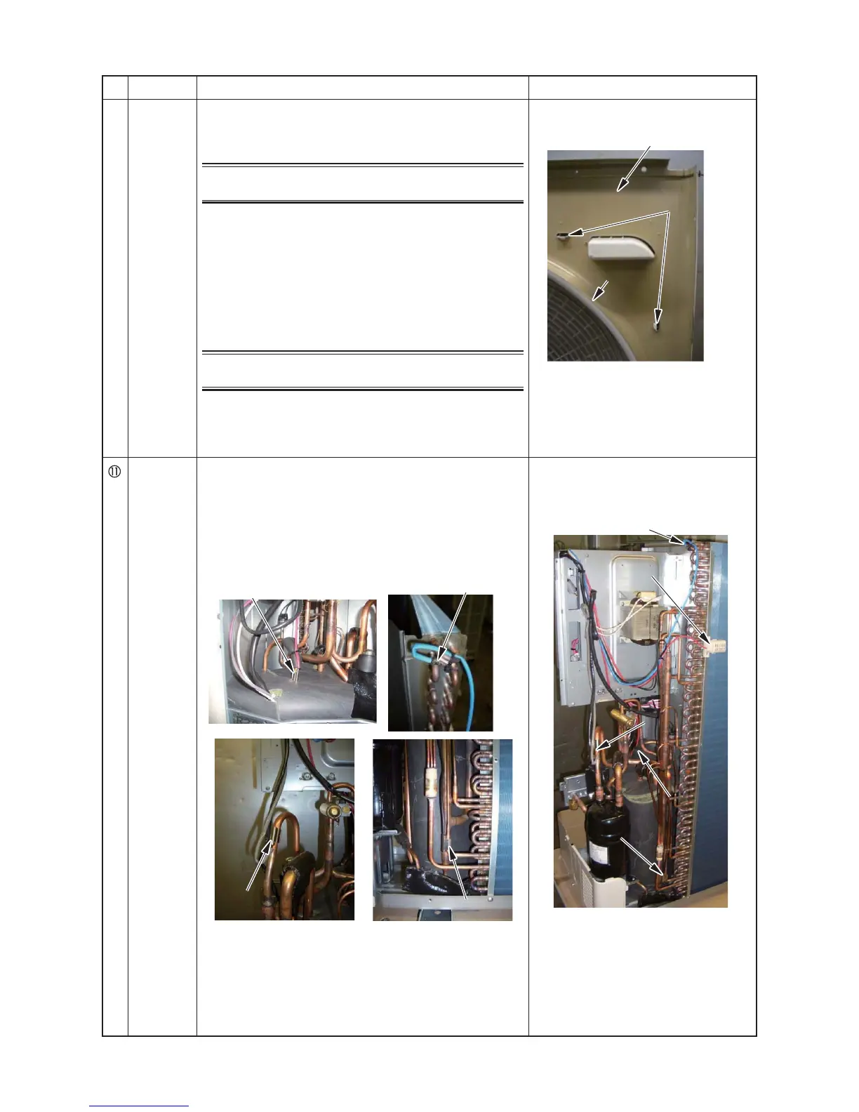
[Reference]
Sensor
mount
positions
1) TD sensor: discharge pipe
2) TL sensor: heat exchanger upside
3) TS sensor: 4-way valve - between accumulator
4) TE sensor: lowest capillary joint
5) TO sensor: Heat exchange surface
Discharge cabinet
Hooking claw
 Loading...