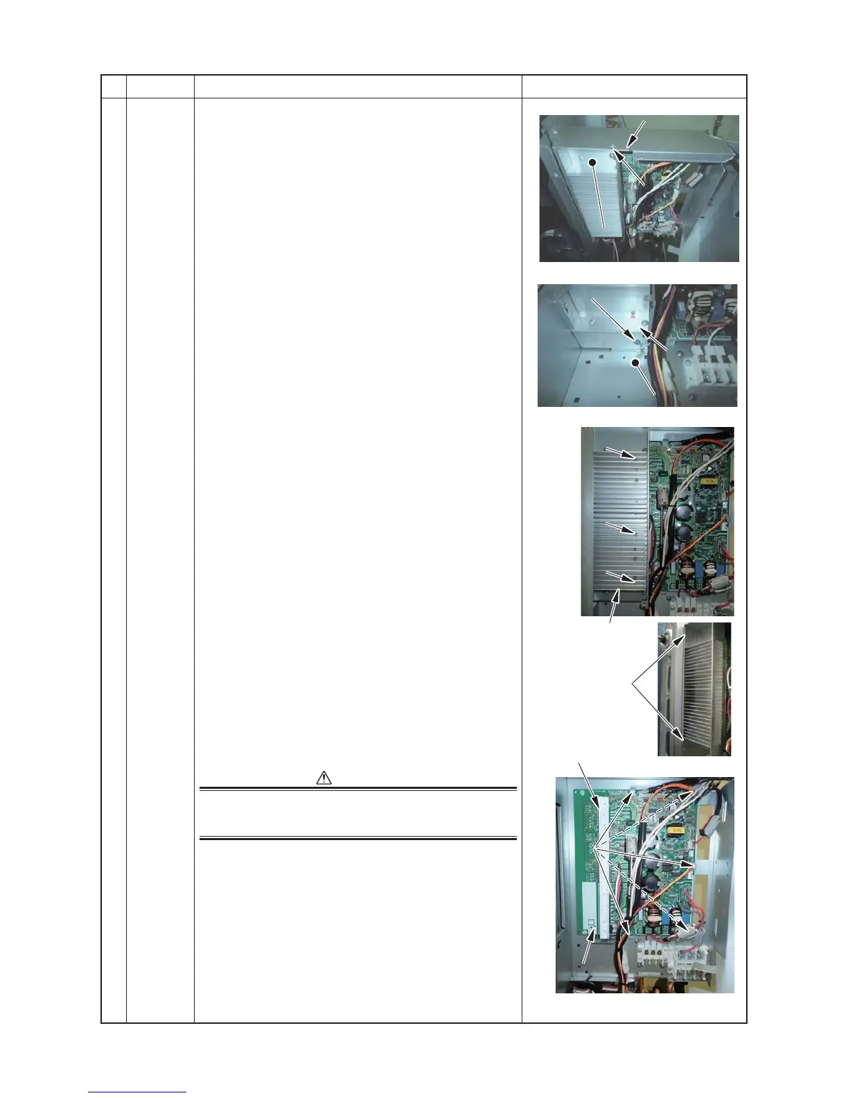
Inverter box
Heat sink duct and
Inverter box fixing
screw
Heat sink duct
Heat sink duct and
Inverter box fixing
screw
Heat sink duct
Inverter box
Heat sink screw
Heat sink screw
Heat sink screw
Supporters
Control P.C. board
15) Remove the heat sink screw.
(Ø3×14, 3 PCS)
16) Remove the inverter box claw being hooking the heat
sink duct to remove the heat sink from control board
assembly.
(The heat sink can be removed with the heat sink duct
attached.)
It may not be easily to remove the heat sink because
the heat sink silicon is coated between the heat sink
and sab-heat sink.
If dusts or scratches on the surface of the sub-heat
sink or heat sink on the removed P.C. board.
CAUTION
If dusts or scratches on the surface of the sub-heat sink or
heat sink on the removed P.C. board occur, be careful to
work as heat dissipation occur, cause the malfunction.
17) Remove the control board assembly.
(Supporter 5 positions)
2. Attachment (Control board)
Attach the control board in the reverse process of
“1. Detachment”.
*3.Coat the heat sink on the control board assembly with
the heat sink silicon uniformly before installing the heat
sink.