– 114 –
No. Part name Procedure Remarks
g
Electric
part
(Reactor)
3. Detachment (Reactor)
1) Following to work of Detachment of
f
2) Remove the connector of the reactor lead wire
connected to the reactor. (2 positions)
3) Remove the connector.
( Ø4 ST3T, 2 pcs,)
4. Attachment (Reactor)
Attach the reactor in the reverse process of the
“3. Detachment (Reactor)”.
Reactor
Reactor lead × 2
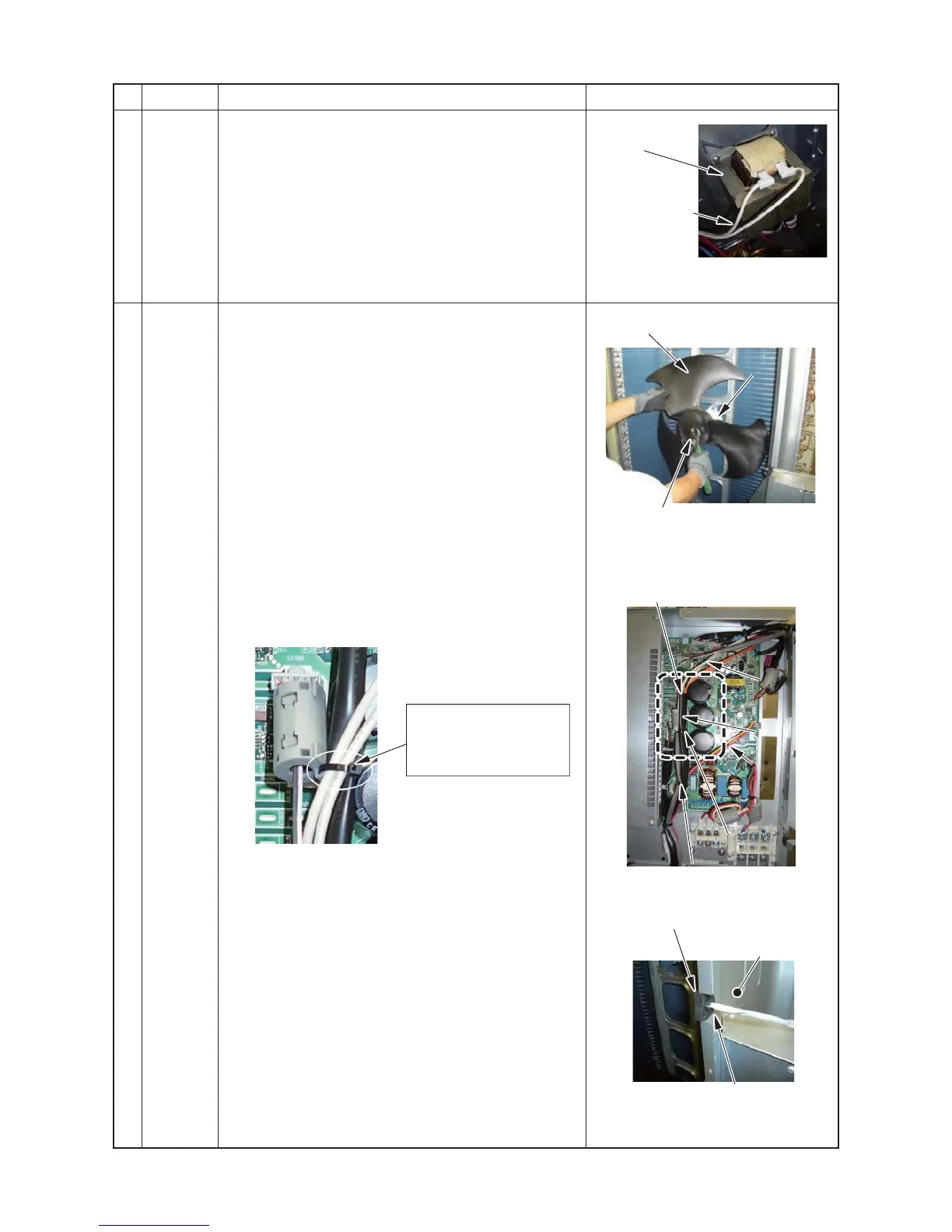
h
Fan motor
1.Detachment
1) Following to work of Detachment of
c
,
d
and
e
.
2) Make sure that the fan motor and the propeller fan
stop.
Remove the flange nut from the fan motor and
propeller fan.
• Loosen the flange nut by turning clock wise.
(To tighten the flange nut, turn it counter clockwise)
3) Remove the propeller fan.
4) Following to work of Detachment of
g
, 1) to 5).
Propeller fan
Reactor lead
(White × 2)
Pass the binding band A4
through the hole on the
clamp filter, and then
bundle two reactor leads.
[Detail.C]
5) Cut the binding band A4 ( Thickness :1.1 mm, Width
:2.5 mm) bundling the case thermostat lead and the
reactor lead × 2
6) Remove the connector for the fan motor lead.
Remove the clamp filter from the fan motor lead.
(It is used after replacement.)
7) Remove the fan motor lead from the fixing rubber for
separate plate.