– 115 –
No. Part name Procedure Remarks
h
Fan motor
(Continued)
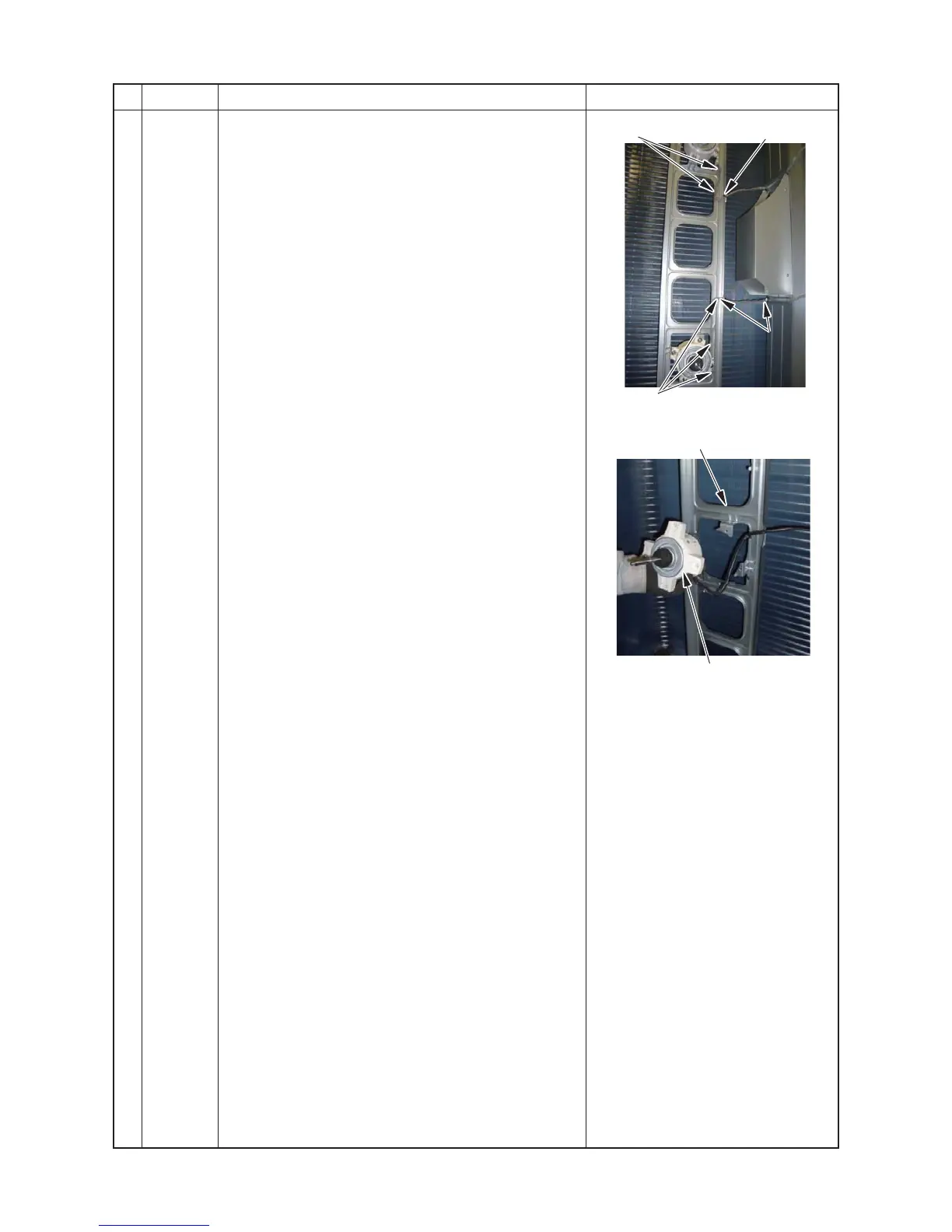
8) Cut the binding band for the air duct fixing fan motor
and the motor base ( 2 position ).
For upper fan motor: one at the motor base
For lower fan motor: one at the motor base
one at the air duct
Loose the claw on the fan motor base (2 positions)
For upper fan motor: 2 positons
For lower fan motor: 3 positions
9) Loosen the 2 claws on the motor base.
10)Remove the fixing screws (4 positions) while holding
the fan motor so as not to fall it.
(Shoulder screw with captive washer Ø4 × 20 4 Each
4Pcs)
2. Attachment
Attach the Fan motor in the reverse process of
“1. Detachment”.
∗ Precautions when assembling the fan motor
• Tighten the flange nut to 4.95 N•m (50 kgf·cm).
• To prevent the fan motor leads from coming in contact
with the propeller fan ensure to adjust the length of the
fan motor lead fixing rubber so that the fan motor lead
has no slack.
Attach the fan motor lead fixing rubber to the separate
plate so that the projection is on the refrigeration cycle
side.
• Ensure to bundle again with a commercially available
code clamp where the code clamp was removed.
• Fix the clamp filter again in the place where it has been
removed.
Claw
Claw
(Lower fan motor)
Binding band