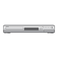
14
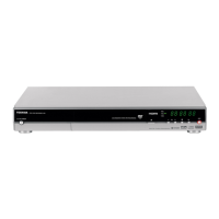
Index to Parts and Controls (Continued)
Introduction
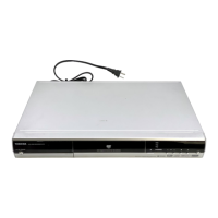
Rear Panel
6 RF IN (FROM ANT.) input socket page 14 in
“INSTALLATION GUIDE”
Connects to an aerial or satellite signal.
7 RF OUT (TO TV) output socket
page 14 in
“INSTALLATION GUIDE”
Connects the supplied coaxial cable to a TV.
8 CHANNEL CHANGE IR jack
page 48 in
“INSTALLATION GUIDE”
Connect the supplied IR control cable to control
cable/satellite channels according to timer
programs.
9 DIGITAL BITSTREAM/PCM COAXIAL AUDIO
OUTPUT jack
page 20 in “INSTALLATION
GUIDE”
Use this to connect the recorder to an audio
receiver equipped with a coaxial digital audio input
jack.
1AC IN socket page 15 in “INSTALLATION
GUIDE”
Connects to the supplied power cord.
2Ventilation fan
3 VIDEO OUTPUT, AUDIO OUTPUT jacks
page 16 in “INSTALLATION GUIDE”
Outputs video and audio signals to a connected
TV or amplifier.
4 Component VIDEO OUTPUT jacks
page 17
in “INSTALLATION GUIDE”
Outputs video signals to a connected TV or
monitor.
Connects to a TV or monitor equipped with
component video jacks.
5AV1(AUDIO/VIDEO)IN/OUT socket
page 39
• Use this socket when connecting the TV that has
the terminal in this shape.
• Use this socket when connecting the video or
other equipment that has the terminal in this
shape.
1 2 3 4 5 6
8
7
9
10 11
RD-XS34SB_Ope_E_p012-019 12/18/04, 5:41 PM14
 Loading...