TCS-NET General Purpose Interface
Installation Manual
Toshiba
–12–
6 Setting
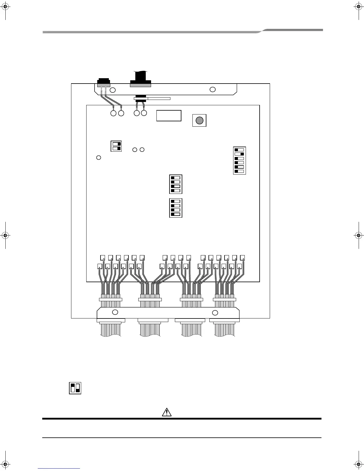
1. Setting Terminator Resistor for the TCC-LINK Communication Line
The TCC-LINK consists of TCB-IFCG1TLE units only. When no multiple air conditioners or custom air conditioners
are connected, set SW6-1 of only one TCB-IFCG1TLE unit to ON and insert a 100-ohm terminator resistor into the
TCC-LINK bus. SW6-2 is not used.
CAUTION
Switch settings are ONLY registered at power ON and when the reset switch has been pressed. When changing
DIP Switch settings, be sure to either power down, or press reset switch SW7 to enable changes to be registered.
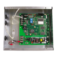
LED POWER
LED TCC-LINK (YELLOW)
LED TCC-LINK ERROR (RED)
SW6
SW5
SW7
SW1
SW2
U2
U1
+
-
AI4+-
AI4-
AI6-
AI6+
AO3-
AO3+-
SWART
CN5
AI3-
AI5+
AI5-
AI3+-
AO2+- AO2-
RO1-RO1+
RO3+RO3-
RO2-
RO2+
RO4+RO4-
DI1+
DI1-
DI3+ DI3-
DI5+DI5-
DI2+
DI2-
DI4+ DI4- DI6+
DI6-
-
SW6
12
ON
OFF
11-EN
+00DE89308101_01EN_TCB-IFCG10TLE_gene_IM.book Page 12 Monday, December 15, 2008 3:49 PM
 Loading...