TCS-NET General Purpose Interface
Installation Manual
Toshiba
–17–
EN
(*1) Can be controlled by the central control remote controller, BMS central controller (such as the 64-way central
control remote controller, or Modbus (TCB-IFMB640TLE). When DI3 contact input is ON, no transfer pulse is
output even if ON instruction is issued. When DI3 contact input is OFF, no transfer pulse is output even if OFF
instruction is issued. At this time, Relay 2 control through Modbus (TCB-IFMB640TLE) is disabled.
(*2) Status request response indicates the contact state, but does not indicate the DI3 state.
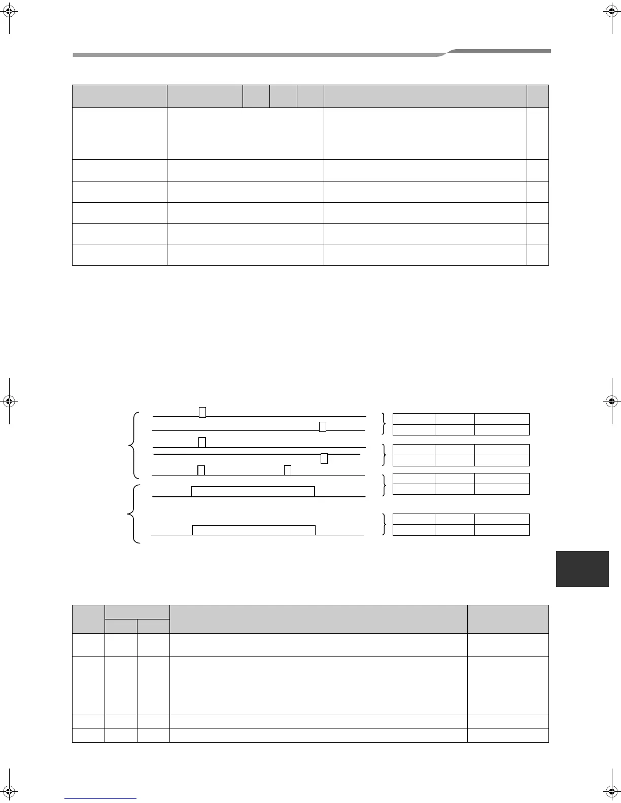
2. Connecting Relay-Controlled Devices
With respect to relay contacts of TCB-IFCG1TLE, there are four output types of the ON set signal and OFF reset
signal sent to a device to be controlled, as described in “1. Functions.” Choose the most suitable type. For details,
see the examples of relay circuit and the description of functions.
The figure below shows the states of relay contacts of RO1, RO2, RO3, and RO4.
3. Functions of DI4 and DI1 (TCB-IFCG1TLE only)
The input states of the DI4 and DI1 ports can be acquired through the Modbus (TCB-IFMB640TLE) interface.
Indoor units can be controlled (for operation stop, etc.) according to the DI4 and DI1 input states by the setting for
Case 2 in the following table.
DI5
(TCB-IFCG1TLE only)
On/off input for general purpose interface Used for Relay 1 ON/OFF input setting at hand. This signal
switches on and off of Relay 1 when DI5 is opened for more
than 100 ms and then closed for 100 ms. The output mode
depends on SW5-1, -2 and -3. However, when the on-hand
setting is disabled through TCC-LINK, this port setting is
not available.
IN
DI6
(TCB-IFCG1TLE only)
Alarm input for general purpose interface Alarm input
Closed signal indicates an alarm
IN
DI4
(TCB-IFCG1TLE only)
Din2 input for general purpose interface Din2 input
IN
DI1
(TCB-IFCG1TLE only)
Din3 input for general purpose interface Din3 input
IN
DI2
(TCB-IFCG1TLE only)
Din4 input for General Purpose I/F Din4 input
IN
DI3 Din1 input for general purpose interface HA
input
HA monitor input. Closed signal shows operation and open
signal shows operation stop.
IN
Case
SW5-
Functions of DI4 and DI6 Local linkage
-5 -6
1OFFOFF
DI4 and DI1 input states can be acquired through the Modbus (TCB-
IFMB640TLE) interface.
Not provided
2ONOFF
DI4 and DI1 input states can be acquired through the Modbus (TCB-
IFMB640TLE) interface.
When the DI4 input state has changed from “Open” to “Closed” it is notified
simultaneously through the TCC-LINK line to turn off all indoor units.
When the DI1 input state has changed from “Open” to “Closed”, all indoor units
of group address 1 are turned off through the TCC-LINK line.
Provided
3 OFF ON SWART entry setup mode Provided
4ONONReserved
Connector Signal name
SW5
-2
SW5
-3
SW5
-4
Operation
In/
Out
SW5-2
ON
SW5-3
OFF
SW5-4
Don’t care
off: relay open
off: relay close
Off :relay open
Off :relay open
on: relay close
on: relay close
off: relay close
Static type
Pulse type
On: relay close
On: relay close
off
off
RO1
RO2
RO1
RO2
RO1
RO2
close
open
on: relay close open
open
open
RO1,RO2,RO3,RO4
SW5-2
OFF
SW5-3
ON
SW5-4
OFF
SW5-2
OFF
SW5-3
OFF
SW5-4
OFF
SW5-2
OFF
SW5-3
ON
SW5-4
ON
16-EN
+00DE89308101_01EN_TCB-IFCG10TLE_gene_IM.book Page 17 Monday, December 15, 2008 3:49 PM
 Loading...