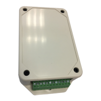
TCS-NET General Purpose Interface
Installation Manual
Toshiba
–24–
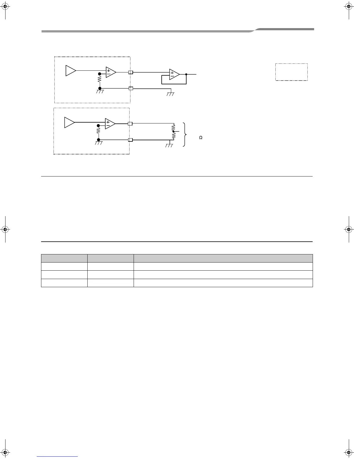
▼ Examples of analog output
Advanced conjunction function
Set SW5-5 to OFF and SW5-6 to ON.
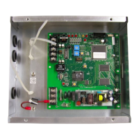
Connect the SWART connector CN5 on this board to the RS232C connector of the PC, and download several
setting files to this product from the dedicated PC tool software. Then collaborative operation among various input
ports, air conditioners, and relay contacts RO1 to RO4 can be set in detail.
For how to download the setting files and their contents, see the manual specified separately.
For the detail data, contact your dealer.
Indication of LEDs
The following LEDs light as follows:
LED No. LED color Lighting condition
D10 Red Lights while power is supplied to this board.
D11 Yellow Lights for 0.5 seconds during TCC-LINK transmission.
D12 Red Lights while TCC-LINK transmission is halted.
DA Converter
AO2,AO3
DA Converter
AO2,AO3
AO2-,AO3-
20K
more than
AO2-,AO3-
buffer
Board side
o
e
23-EN
+00DE89308101_01EN_TCB-IFCG10TLE_gene_IM.book Page 24 Monday, December 15, 2008 3:49 PM
 Loading...