10
E6582171
Table 2-2. Internal circuit
2.2.3 Signaling
Following type resolver is applicable for this option.
- Excitation frequency: 3 to 12 kHz
- Transformation ratio: 0.5
- Pole number: 2
Recommended resolver is RTD4A4Y2 P1 7 10 0.5 D2SR12 12 (Baumer).
As for the resolver signals, connect S1-S4 and R1, R2 with the same terminal on your resolver.
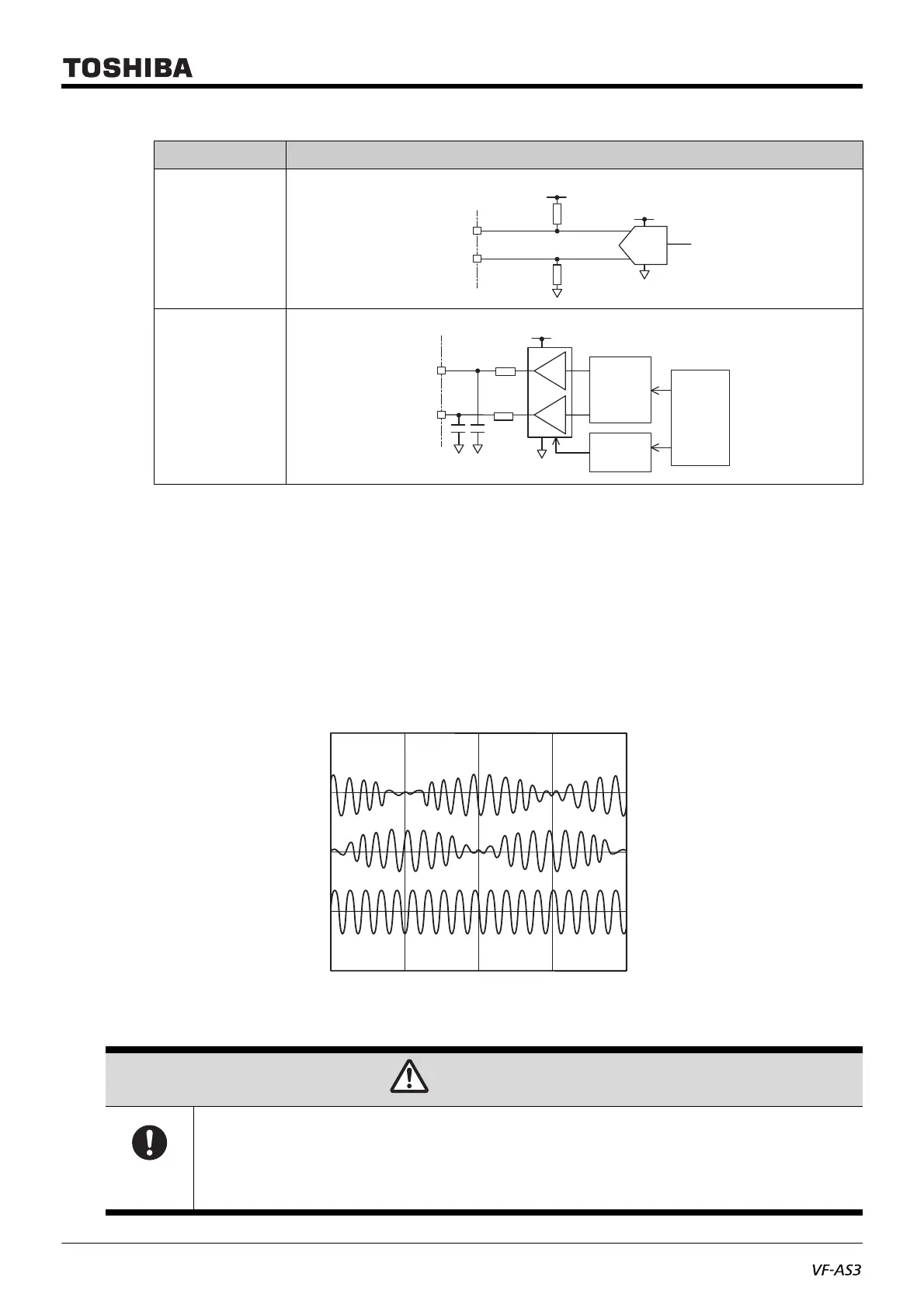
The signal feedback from the resolver should have the waveform shown in Fig.1 (S2-S4 should have
90degree phase difference from S3-S1) in terms of the motor rotation direction. The resolver installation
direction and signal wiring should be done accordingly.
Fig.1 - Resolver format signal
Circuit diagram
(a)
(b)
CAUTION
Mandatory
action
• Use the resolver with the specification described in this manual.
Improper resolver usage can result in accident and malfunction.
• Forward rotation or reverse rotation is judged from the resolver feedback signals of S2-S4 and S3-S1.
Make sure that the connection correctly. Wrong connection can cause an accident due to unintended
rotation of the motor.
R2
VDD
4.7
4.7
R1
Controller
Reference
oscillator
Gain
controller
0º
R2 – R4
S3 – S1
S2 – S4
90º 180º 270º 360º

 Loading...


