| English
16
OPERATION
Install the front handle as shown in the picture below. Be sure to orient the stem
toward the hole. Do not fasten the screws until you have set the most comfortable
working position with the straps. The front handle must be oriented as shown in the
picture for "the motor and drive unit".(See Figure A)
Install the desired tube on the bar of the main unit. Be sure that the locking pin is
inserted in the hole of the bar
Fix the bar by turning the nut anticlockwise. (See Figure B)
Carter of protection (Brush cutter and grass trimmer)
(See Figure C)
Remove the two screws from the carter of protection.
On the tube of the brush cutter/grass trimmer, place the carter of protection on its
support.
Screw the carter of protection with the two screws.
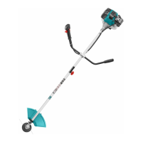
3-theethes blade for brush cutter (See Figure D)
On the tube of the brush cutter/grass trimmer, insert a metal locking tool into the
hole on the side of the drive gear and on the tool drive.
Remove cover bell and the holding nut from the shaft.
Install, in the following order, on the shaft: the blade, the cover bell and then the
holding nut.
Remove the metal locking tool.
To remove the metal blade, put a metal locking tool into the hole on the side of the
drive gear and on the tool drive. Unscrew the holding nut and then remove the cover
bell and the blade.
Cutting head for grass trimmer (See Figure E)
On the tube of the brush cutter/grass trimmer, insert a metal locking tool into the
hole on the side of the drive gear and on the tool drive.
Remove cover bell and the holding nut from the shaft.
Install and screw the nylon cutting head. Make that it is well installed.
Remove then the metal locking tool.