Manufacturer reserves the right to
discontinue, or change at any time,
specifications or designs without notice
and without incurring obligations.
REPLACEMENT COMPONENTS DIVISION LITERATURE NUMBER P274-8SI
© CARRIER CORPORATION 2007 1-07 REPLACES: NEW
PRINTED IN U.S.A. CATALOG NUMBER 570-502
Part No. P274-1100, 1200, 1300
CONTENTS
Page
SAFETY CONSIDERATIONS . . . . . . . . . . . . . . . . . . . . . . 1
GENERAL . . . . . . . . . . . . . . . . . . . . . . . . . . . . . . . . . . . . . . . . 1
INSTALLATION CONSIDERATIONS . . . . . . . . . . . . . .1,2
Models . . . . . . . . . . . . . . . . . . . . . . . . . . . . . . . . . . . . . . . . . . . 1
Outdoor Temperature Sensing . . . . . . . . . . . . . . . . . . . 1
INSTALLATION . . . . . . . . . . . . . . . . . . . . . . . . . . . . . . . . 2-14
Step 1 — Thermostat Location . . . . . . . . . . . . . . . . . . . 2
Step 2 — Set DIP Switches . . . . . . . . . . . . . . . . . . . . . . . 2
Step 3 — Install Thermostat . . . . . . . . . . . . . . . . . . . . . . 2
Step 4 — Space Temperature Averaging . . . . . . . . 10
Step 5 — Set Thermostat Configuration . . . . . . . . . 10
Step 6 — Check Thermostat Operation. . . . . . . . . . 12
Step 7 — Select Thermostat Operation
Settings. . . . . . . . . . . . . . . . . . . . . . . . . . . . . . . . . . . . . . . 13
Step 8 — Set Current Time . . . . . . . . . . . . . . . . . . . . . . 13
Step 9 — Set Current Day . . . . . . . . . . . . . . . . . . . . . . . 13
Step 10 — Programming Thermostat
Schedules . . . . . . . . . . . . . . . . . . . . . . . . . . . . . . . . . . . . 13
Step 11 — Final Checklist . . . . . . . . . . . . . . . . . . . . . . . 13
OPERATION. . . . . . . . . . . . . . . . . . . . . . . . . . . . . . . . . . .14,15
Hold, Fan, and Mode Button Operation . . . . . . . . . . 14
Outdoor Temperature . . . . . . . . . . . . . . . . . . . . . . . . . . . 14
Thermostat Output Assignments. . . . . . . . . . . . . . . . 14
Five-Minute Compressor Timeguard . . . . . . . . . . . . 14
Fifteen-Minute Cycle Timer. . . . . . . . . . . . . . . . . . . . . . 14
Fifteen-Minute Staging Timer. . . . . . . . . . . . . . . . . . . . 14
Three-Minute Minimum On Time . . . . . . . . . . . . . . . . 14
Heating/Cooling Set Points. . . . . . . . . . . . . . . . . . . . . . 14
Auto-Changeover Timer . . . . . . . . . . . . . . . . . . . . . . . . . 14
Power-On Check . . . . . . . . . . . . . . . . . . . . . . . . . . . . . . . . 14
Error Codes . . . . . . . . . . . . . . . . . . . . . . . . . . . . . . . . . . . . . 15
Smart Recovery (Heating Mode Only) . . . . . . . . . . . 15
TROUBLESHOOTING. . . . . . . . . . . . . . . . . . . . . . . . . . . . 15
PROGRAMMABLE THERMOSTAT
CONFIGURATION RECORD . . . . . . . . . . . . . . . . . . . 16
SAFETY CONSIDERATIONS
Read and follow manufacturer instructions carefully. Fol-
low all local electrical codes during installation. All wiring
must conform to local and national electrical codes. Improper
wiring or installation may damage the thermostat.
Recognize safety information. This is the safety alert sym-
bol . When the safety alert symbol is present on equipment
or in the instruction manual, be alert to the potential for person-
al injury.
Understand the signal words DANGER, WARNING, and
CAUTION. These words are used with the safety alert symbol.
DANGER identifies the most serious hazards which will result
in severe personal injury or death. WARNING signifies a haz
-
ard which could result in personal injury or death. CAUTION
is used to identify unsafe practices which would result in minor
personal injury or property damage.
GENERAL
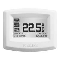
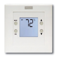
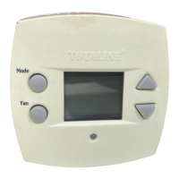
Totaline® 7-day, programmable thermostats are wall-mount-
ed, low-voltage thermostats which maintain room temperature
by controlling the operation of an HVAC (heating, ventilation,
and air-conditioning) system. Separate heating and cooling set
points and auto-changeover capability allow occupied and un
-
occupied programming for energy savings.
All programmable thermostats allow up to 4 time/tempera-
ture settings to be programmed per 24-hr period. Each thermo-
stat stores programs for 7 independent days. Batteries are not
required. During power interruption, the internal memory
stores comfort schedules for an unlimited time while the clock
continues to run for at least 72 hours.
INSTALLATION CONSIDERATIONS
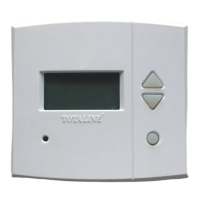
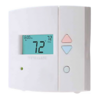
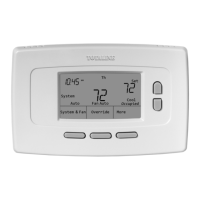
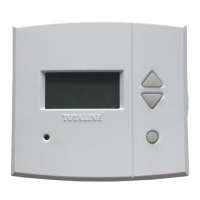
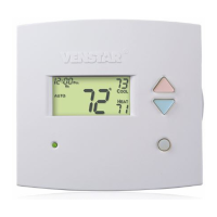
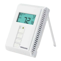
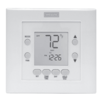
Models — There are 3 different models. Ensure the proper
thermostat is selected for the intended application. Refer to
Fig. 1 for thermostat dimensions. Select from the following
models:
1. P274-1100 (air conditioner [AC]) — 1-stage cool,
1-stage heat for air-conditioning systems only
2. P274-1200 (heat pump [HP]) — 1-stage cool, 2-stage
heat for either heat pump or air conditioner systems
with 2-stage heat
3. P274-1300 (2-speed) — 2-stage cool, 2-stage heat for
2-speed AC systems, or 2-stage cool, 3-stage heat for
2-speed HP systems, or 1-stage cool, 4-stage heat for
1-speed HP with special 3-stage electric heat
Outdoor Temperature Sensing — All programma-
ble thermostats can be equipped with an optional outdoor tem-
perature sensor, part no. TSTATXXSEN01-B. If this option is
to be installed, plan thermostat installation so that 2 wires can
be run from the thermostat to an outdoor location. Refer to the
installation instructions provided with the outdoor temperature
sensor for necessary connections.
IMPORTANT: Read entire instructions before start-
ing the installation.
INSTALLATION
AND OPERATING
INSTRUCTIONS
Residential
Programmable
Thermostats
TOTALINE
1c.eps
gold-1.pdf