Do you have a question about the TP-Link EAP223 and is the answer not in the manual?
Overview of the front panel, including LED indicator status for initialization and operation.
Details rear panel ports (ETH1, ETH2) and the reset function for factory defaults.
Step-by-step guide for mounting the EAP onto a ceiling tile using provided hardware.
Instructions for installing the EAP on a wall, including anchor and screw usage.
How to power the EAP using a PoE switch via the ETH1 port.
Steps to power the EAP using a PoE adapter and connecting to a LAN.
Instructions for powering the EAP using a standard power adapter via the POWER port.
Configuration method for managing EAPs individually, using Omada App or Web Browser.
Detailed steps for configuring EAPs in standalone mode using the Omada mobile application.
Instructions for configuring EAPs in standalone mode via a web browser.
Methods for managing EAPs collectively via Omada Software or Hardware Controller.
Steps to configure Omada Controller (Software/Hardware) using the Omada mobile application.
Instructions for configuring Omada Controller via a web browser.
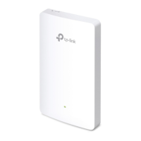
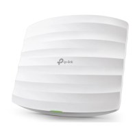
The TP-Link Omada Wireless Access Point is a versatile networking device designed for both ceiling and wall mounting, offering robust wireless connectivity and centralized management capabilities. It supports various power supply options and can be configured in either standalone or controller mode, making it suitable for a range of network environments from small setups to large-scale deployments.
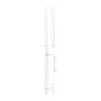
The primary function of this device is to provide wireless network access. It acts as an access point, extending the reach of an existing network and allowing wireless clients to connect. The device supports both 2.4GHz and 5GHz wireless bands, indicated by the default SSID format (TP-Link_2.4GHz/5GHz_XXXXXX), ensuring compatibility with a wide range of wireless devices and offering flexible performance options.
For power supply, the EAP can be powered through a PoE (Power over Ethernet) switch or a PoE adapter, which simplifies installation by allowing both power and data to be transmitted over a single Ethernet cable. Specific models like EAP115, EAP225, EAP223, EAP245, and EAP265 HD support PoE via a switch, while EAP110, EAP225, EAP223, EAP245, and EAP265 HD can use a PoE adapter. The EAP115 also has the option of being powered by a traditional power adapter plugged into a standard electrical wall outlet. This flexibility in power options caters to different installation scenarios and existing infrastructure.
The device offers two main software configuration modes: Standalone Mode and Controller Mode. In Standalone Mode, each EAP is configured and managed individually, which is convenient for small networks with only a few devices. In Controller Mode, EAPs can be configured and managed in batches from a central platform using the Omada Controller (either Software Controller or Hardware Controller). This centralized management is ideal for larger networks, providing simplified deployment, monitoring, and maintenance.
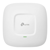
The device features an LED indicator on the front panel that provides visual feedback on its operational status. A solid green light indicates that the device is initializing or working properly. Slowly flashing green signifies an isolated state, while flashing yellow indicates abnormal operation. Flashing yellow and green together means the device is updating, and it's crucial not to disconnect or power off during this state. Quickly flashing yellow and green indicates that the device is being reset to its factory default settings.
On the rear panel, the device includes an Ethernet port. For models like EAP225, EAP223, EAP245, and EAP265 HD, this port is labeled ETH1 (PoE) and is used for both data transmission and Power over Ethernet. EAP245 and EAP265 HD models also feature an ETH2 port, which is a Gigabit Ethernet port used for bridging. Notably, for EAP245 V4, ETH2 supports Passive PoE Out, with a power consumption limit of 5W for downlink terminal devices. For EAP110 and EAP115, the Ethernet port serves a similar function for data and PoE. The EAP115 also has a dedicated POWER port for its power adapter.
The device is designed for easy installation, supporting both ceiling and wall mounting. The mounting bracket facilitates secure attachment. For ceiling mounting, the bracket is secured to a ceiling tile using M3x30 pan-head screws, washers, and wing nuts. For wall mounting, M3x28 plastic wall anchors and M3x20 self-tapping screws are used. The design ensures that the EAP can be easily attached and detached from the mounting bracket by aligning arrow marks and rotating, with a security slot for releasing a locking tab when removal is needed.
The Omada Wireless Access Point is designed for user-friendly setup and operation. Video tutorials are available online (via a link or QR code) to guide users through the installation process.
In Standalone Mode, configuration can be done via the Omada App or a web browser. Using the Omada App, users download the app, connect to the EAP's default SSID, and then configure the device directly. For web browser configuration, users connect to the EAP's default SSID, navigate to http://tplinkeap.net, log in with default credentials (admin/admin), set a new username and password, and then modify wireless parameters.
In Controller Mode, the Omada Software Controller can be installed on a Windows or Linux PC, or the Omada Hardware Controller (OC200/OC300) can be used. The Software Controller requires a PC to be continuously running, while the Hardware Controller is a dedicated device. Both offer centralized management. Configuration in Controller Mode can also be done via the Omada App or a web browser. For app-based configuration, users download the Omada App, then either manage locally (connecting to the EAP's SSID and adding the controller) or remotely (logging in with a TP-Link ID and accessing the controller via Cloud Access). For web browser configuration, users access the controller's web page (either directly for Software Controller or by finding its IP address via the router's DHCP client list for Hardware Controller), complete a quick setup wizard, and then log in. Remote management via Omada Cloud Service is also supported, requiring Cloud Access to be enabled on the controller and bound to a TP-Link ID.
The device includes a RESET button for easy restoration to factory default settings. By pressing and holding the button for about 5 seconds until the LED flashes yellow then green, the device will reset. This is useful for troubleshooting or reconfiguring the device from scratch.
The Omada ecosystem provides comprehensive support for maintenance. User guides for both the controller and EAPs are available on the TP-Link official website, offering detailed configurations and troubleshooting steps. The TP-Link Community forum is also available for users to ask questions, find answers, and interact with other users or engineers. Technical support and additional information can be accessed via the TP-Link support website or by scanning a QR code.
Safety information is also provided, emphasizing the importance of keeping the device away from water, fire, humidity, and hot environments. Users are advised not to disassemble, repair, or modify the device and to contact support if service is needed. It also highlights the importance of using recommended chargers and avoiding use in areas where wireless devices are not allowed. The adapter should be installed near the equipment and be easily accessible.
The device's software may include code developed by third parties under the GNU General Public License (GPL), with information on accessing this code available on the TP-Link website.
| Brand | TP-Link |
|---|---|
| Model | EAP223 |
| Category | Wireless Access Point |
| Language | English |