Do you have a question about the TP-Link EAP245 and is the answer not in the manual?
Instructions for mounting the EAP using a ceiling T-rail clip and screws.
Steps for attaching the EAP bracket to a ceiling tile for mounting.
Guide for securely mounting the EAP to a wall using anchors and screws.
Connect the EAP to a PoE switch using an Ethernet cable for power and data.
Connect the EAP to a power adapter and wall outlet for power supply.
Download and install the EAP Controller software on the management host.
Launch the controller, create a wireless network, and log in.
Adopt EAP devices within the Controller interface to manage them.
Refer to the EAP Controller User Guide for advanced configuration details.
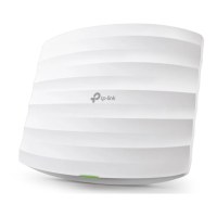
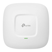
The TP-Link AC1750 Wireless Dual Band Gigabit Access Point, model EAP245, is a networking device designed to provide robust and scalable wireless connectivity, particularly suitable for business environments. It functions as an access point, extending a wireless network and allowing multiple clients to connect to the internet or a local network.
The EAP245 operates as a central hub for wireless communication, taking an existing wired network connection and broadcasting a Wi-Fi signal. It supports dual-band operation, meaning it can transmit Wi-Fi signals on both the 2.4 GHz and 5 GHz frequency bands simultaneously. This capability allows for greater flexibility and performance, as the 2.4 GHz band offers wider coverage, while the 5 GHz band provides faster speeds and less interference, ideal for bandwidth-intensive applications. The "Gigabit Access Point" designation indicates that its Ethernet port supports Gigabit speeds, ensuring that the wired connection to the network backbone does not bottleneck the wireless performance.
The device is designed to be part of a larger network infrastructure, often managed by an EAP Controller. This controller software, installed on a management host, allows for centralized management of multiple EAP devices, simplifying the setup, configuration, and monitoring of a large-scale wireless network. This is particularly beneficial in scenarios like offices, hotels, or educational institutions where numerous access points are required to cover a wide area. The EAP Controller enables features such as unified Wi-Fi network creation, guest network management, and detailed network statistics.
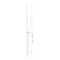
The EAP245 offers flexible power options, enhancing its versatility in deployment. It can be powered either via a Power Sourcing Equipment (PSE) device, such as a PoE (Power over Ethernet) switch, or through a standard power adapter. Power over Ethernet simplifies installation by allowing both power and data to be transmitted over a single Ethernet cable, reducing cable clutter and enabling placement in locations where power outlets might not be readily available. When using a PoE switch, a single Ethernet cable connects the EAP to the switch, handling both data transmission and power delivery. Alternatively, for setups without PoE, a standard electrical wall outlet can be used with the provided power adapter.
The device features a single ETHERNET port, which serves a dual purpose: connecting to a router or switch for data transmission and, if using PoE, receiving power from a PSE. This integration streamlines the cabling requirements.
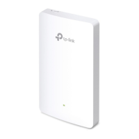
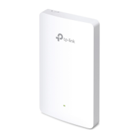
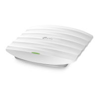
Installation flexibility is a key aspect of the EAP245's design. It supports three primary mounting options: ceiling rail mounting, ceiling mounting, and wall mounting. This adaptability allows the device to be discreetly integrated into various environments. For ceiling rail mounting, a dedicated clip secures the device to a T-rail, commonly found in suspended ceiling systems. Ceiling mounting involves attaching a bracket directly to the ceiling tile, often requiring drilling holes for screws and for the Ethernet cable. Wall mounting, similarly, uses a bracket secured to a wall with anchors and screws. The design ensures that once mounted, the EAP can be easily attached and rotated into place on its bracket, locking securely. The mounting process is designed to be straightforward, with clear instructions for each option, including the necessary hardware like screws, washers, and wall anchors.
The EAP245 is intended to be configured and managed through the EAP Controller software. The initial setup involves downloading and installing the EAP Controller on a management host. Once installed, a configuration wizard guides the user through creating a primary wireless network, setting up admin credentials, and logging into the controller interface. The controller then allows for "adopting" EAP devices, changing their status from "Pending" to "Connected," and integrating them into the managed network. This centralized management simplifies the deployment and ongoing administration of multiple access points, enabling uniform configuration and monitoring across the entire wireless infrastructure.
The EAP245 incorporates LED indicators to provide immediate visual feedback on its operational status, aiding in quick troubleshooting and monitoring. A solid green light indicates that the device is working properly, signifying normal operation. A flashing yellow light signals that a firmware update is in progress, alerting users not to disconnect or power off the device during this critical process to prevent potential damage. A flashing red light indicates system errors, which could be related to RAM, Flash memory, Ethernet connectivity, WLAN functionality, or firmware issues, prompting further investigation. Finally, a double-flashing red, green, and yellow light pattern signifies that the device is undergoing a factory reset, reverting all settings to their default state.
For maintenance and troubleshooting, the device includes a RESET button. This button allows users to restore the EAP to its factory default settings. To perform a reset, the device must be powered on. The user presses and holds the button for approximately 8 seconds until the LED flashes red, then releases it. This feature is crucial for resolving configuration issues or preparing the device for redeployment.
The EAP Controller software itself provides comprehensive tools for ongoing maintenance and management. It allows administrators to view network statistics, monitor device status, and perform various configurations remotely. This centralized control reduces the need for physical access to each access point for routine maintenance tasks. The controller's user guide offers detailed information on configuring and using the software, empowering administrators to effectively manage their wireless network. Firmware updates, which are essential for security and performance improvements, are typically managed through the EAP Controller, ensuring that all connected EAPs can be updated efficiently.
| Frequency Band | 2.4GHz and 5GHz |
|---|---|
| Antenna Type | Internal |
| Maximum Power Consumption | 12.3W |
| Wireless Standard | IEEE 802.11ac/n/g/b/a |
| Ethernet Ports | 1 x Gigabit Ethernet |
| PoE Support | 802.3at PoE |
| Mounting | Ceiling/Wall Mounting |
| Wireless Functions | Band Steering, Airtime Fairness |
| Wireless Security | WPA/WPA2-Enterprise, WPA-PSK/WPA2-PSK |
| Management | SNMP |
| Power Supply | 802.3at PoE or 12V/2A DC |
| Operating Temperature | 0°C to 40°C (32°F to 104°F) |
| Maximum Data Rate | 1750 Mbps (450 Mbps at 2.4 GHz, 1300 Mbps at 5 GHz) |