Do you have a question about the TP-Link EAP660 and is the answer not in the manual?
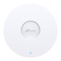
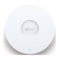
Details the EAP's front panel, including the LED indicator status and function.
Covers rear panel connections, ports, and the reset button function for factory defaults.
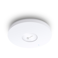
Step-by-step guide for mounting the EAP on a ceiling tile.
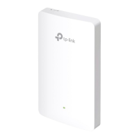
Step-by-step guide for mounting the EAP on a wall.
Connecting the EAP using an 802.3at compliant PoE switch for power and data.
Powering the EAP using the provided power adapter and a wall outlet.
Configure EAPs individually using Omada App or web browser for basic settings.
Centralized management via Omada Software, Hardware, or Cloud Controllers.
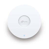
This document describes a Wireless Access Point (EAP) designed for robust network connectivity, offering flexible installation and comprehensive management options.
The EAP serves as a wireless access point, extending network coverage and providing Wi-Fi connectivity to clients. It can be deployed in various environments, from small networks requiring individual management to large-scale setups demanding centralized control. The device facilitates data transmission and, when powered via Power over Ethernet (PoE), also receives power through the same Ethernet cable, simplifying deployment. It supports different Ethernet speeds depending on the model, ensuring compatibility with various network infrastructures.
The EAP offers two primary mounting methods: ceiling mounting and wall mounting.
The EAP can be powered in two ways:
The EAP supports two distinct software configuration modes to cater to different network sizes and management preferences:
http://tplinkeap.net. Here, they can set up a new username and password, modify wireless parameters, and configure basic functions. For advanced functions, Controller Mode is recommended.https://omada.tplinkcloud.com, add their controller, register devices by serial number, and assign licenses to manage and configure them. The Omada App can also be used to manage the cloud-based controller.The EAP features an LED indicator that provides visual feedback on its operational status:
The device includes a reset button that allows users to restore it to factory default settings. To perform a reset, the user must press and hold the button for approximately 5 seconds while the device is powered on, until the LED flashes quickly. Releasing the button will initiate the device's reboot with factory defaults. This is a crucial feature for troubleshooting or reconfiguring the device from scratch.
While not explicitly detailed in the provided text, the "Upgrade" LED flashing pattern suggests that the device supports firmware upgrades. This is a standard maintenance feature for network devices, allowing for performance improvements, bug fixes, and new feature additions over time. These upgrades are typically managed through the Omada controller or the device's web interface.
The manual directs users to various resources for support and troubleshooting:
The manual includes important safety guidelines to ensure proper device operation and user safety:
TP-Link acknowledges that its products may contain software code developed by third parties under the GNU General Public License (GPL). Information on obtaining access to this GPL Code is provided, emphasizing that these programs are distributed without warranty and are subject to the copyrights of their authors.
| Frequency Band | 2.4 GHz and 5 GHz |
|---|---|
| PoE | 802.3at PoE+ |
| MU-MIMO | Yes |
| OFDMA | Yes |
| Beamforming | Yes |
| Operating Humidity | 10% to 90% non-condensing |
| Wireless Standard | 802.11ax |
| Antenna Type | Internal |
| Management | Omada SDN |
| Dimensions | 243 × 243 × 64 mm |
| Mounting | Ceiling/Wall Mounting |
| Security | WPA3 |
| Antenna Gain | 2.4 GHz: 5 dBi, 5 GHz: 6 dBi |
| Operating Temperature | 0–40 ℃ (32–104 ℉) |