20
Stackable L2+/L3 Managed Switch
Connect the console port of the device with your computer by the console cable as the
following figure shown.
Figure 5-3 Connecting the Console Port
You can also manage the device through the console port, for details please refer to the
CLI Reference Guide on the resource CD.
Note:
■
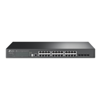
The console port is the first port on the left of the front panel.
■
Please keep the device power off when plugging the console cable.
■
Do not connect the console port with other ports by RJ45 cable.
5.4 Verify Installation
After completing the installation, please verify the following items:
■
There are 5~10cm of clearance around the sides of the device for ventilation and the
air flow is adequate.
■
The voltage of the power supply meets the requirement of the input voltage of the
device.
■
The power socket, device and rack are well grounded.
■
The device is correctly connected to other network devices.
5.5 Power on via Power Supply Module
After the Power Supply Module (PSM150-AC for example) is installed on the switch,
please plug the female connector of the provided power cord into the power socket of
the device, and the male connector into a power outlet as the following figure shows.
Connection
 Loading...

