A Phillips screwdriver
A PoE switch
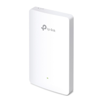
Hardware Overview
Quick Installation Guide
Wireless Wall Plate Access Point
Installation Steps
3
Front Panel
Rear Panel
Pre-Installation Checklist
2
UPLINK+PoE Port
Connected to a PSE (Power Sourcing Equipment), such as a PoE switch, for
both data transmission and Power.
LED/Wi-Fi Button
When the EAP is working in Standalone Mode and enabled with Wi-Fi
Control, press the button to turn on/o both the Wi-Fi and LED. In the other
cases, press the button to turn on/o the LED only.
LAN Port
A wired device can be connected to the LAN port via an Ethernet cable and
access the network.
RESET
With the EAP powered on, press and hold the button for about 5 seconds
until the LED ashes, then release the button. The EAP will restore to factory
default settings.
LED Indicator
On: Working normally/Initializing.
O: Working abnormally/Power o/LED is turned o.
Flashing:
Initialization: The LED ashes twice after initialization is completed.
Upgrade: The LED ashes once per second while upgrading.
Reset: The LED ashes quickly during the reset. The EAP will then reboot.
Locate: When the Locate feature is activated in the Omada controller, the
LED ashes quickly to locate and identify the device. The LED will ash for
10 minutes, or you can disable the feature manually to stop it ashing.
Before installation, be sure that you have the following items:
A pre-installed wall junction box
An RJ45 plug
A triangular screwdriver
The EAP can be mounted into either an 86 mm wall junction box or a standard EU
wall junction box. The junction box should be pre-installed with a running-in-wall
Ethernet cable connected to a PoE switch.
LAN Port
RESET
LED
LED/Wi-Fi Button
5. Press the faceplate of the EAP back into position.
Standard EU wall junction box86 mm wall junction box
4. Insert the enclosed screws and tighten them with a triangular screwdriver
to secure the mounting bracket.
Note:
Do not over tighten the screws.
If the enclosed screws do not t the junction box, use the screws attached to the
junction box instead.
1
Note: The image may dier from the actual product.
Setup with videos
Scan QR code or visit
https://www.tp-link.com/support/setup-video/
1. Detach the faceplate of the junction box with a Phillips screwdriver
(demonstrated with an 86 mm wall junction box).
2. Detach the faceplate of the EAP with a screwdriver.
3. Connect the Ethernet cable inside the junction box to an RJ45 plug. Then
connect the cable to the UPLINK+PoE port. Position the Ethernet cable
to ensure it is not strained.