Do you have a question about the TP-Link TL-POE170S and is the answer not in the manual?
Details the meaning of Power (PWR) and PoE status LEDs on the device.
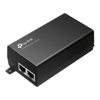
Illustrates the physical connection of PoE injector between powered devices and network.
Details general technical specifications including standards, ports, and power.
Outlines operating and storage conditions, and physical mounting details.
This document provides an installation guide and LED explanation for a PoE Injector, specifically referencing the TL-POE160S and TL-POE170S models. It details the device's function, how to connect it, and offers troubleshooting tips.
A PoE Injector, such as the TL-POE160S or TL-POE170S, serves a crucial role in modern network infrastructure by providing both power and data connectivity over a single Ethernet cable to a powered device (PD). This eliminates the need for a separate power outlet near the PD, offering greater flexibility in device placement and simplifying cabling. The injector acts as an intermediary between an Ethernet device (like a switch or router) and a powered device (such as an IP camera, wireless access point (AP), or IP phone). It receives data from the Ethernet device via its "DATA IN" port and then combines this data with electrical power, sending the combined signal out through its "PWR+DATA OUT" port to the PD. This process allows devices that are compliant with Power over Ethernet (PoE) standards to operate in locations where traditional power sources might be inconvenient or unavailable. The TL-POE170S model, in particular, supports higher power requirements, indicated by its PoE LED, which provides feedback on the power supply status to the connected device.
The PoE Injector is designed for straightforward use, ensuring a seamless integration into existing network setups.
Connection Simplicity: The connection process is intuitive:
LED Indicators for Status Monitoring: The device features LED indicators that provide immediate visual feedback on its operational status:
Compatibility and Flexibility: The PoE Injector is designed to be compatible with various PoE-compliant devices, supporting different power requirements. Its ability to supply power and data over a single Ethernet cable enhances network design flexibility, allowing devices to be placed in optimal locations without being constrained by the proximity of power outlets. The device's RJ45 ports support 10/100/1000 Mbps speeds, ensuring compatibility with a wide range of network devices and supporting gigabit connections.
Troubleshooting Guidance: The manual provides clear guidance for common issues, particularly if the injector fails to supply power or if the power supply is unstable:
While the PoE Injector is largely a plug-and-play device requiring minimal ongoing maintenance, certain practices and considerations contribute to its longevity and reliable operation.
Environmental Considerations: To ensure optimal performance and extend the lifespan of the device, it's important to adhere to recommended environmental conditions:
Physical Integrity and Safety:
Cable Management: Although not explicitly a maintenance feature, proper cable management contributes to the overall reliability and longevity of the network setup. Ensuring that Ethernet cables are not excessively bent, crimped, or strained can prevent damage to the cables and ensure consistent power and data delivery. Using high-quality Ethernet cables, as suggested in the troubleshooting section, is also a preventative measure against unstable power supply.
Firmware Updates (If Applicable): While the manual does not detail firmware updates for this specific device, for many network devices, keeping firmware up-to-date can enhance performance, fix bugs, and improve security. Users should periodically check the manufacturer's support website for any available updates for their specific model.
By following these guidelines, users can ensure the reliable and safe operation of their PoE Injector, maximizing its utility in their network infrastructure.
| Cabling technology | 10/100/1000 |
|---|---|
| Networking standards | IEEE 802.3ab, IEEE 802.3af, IEEE 802.3at, IEEE 802.3bt, IEEE 802.3i, IEEE 802.3u |
| Cable types supported | Cat3, Cat4, Cat5, Cat5e, Cat6 |
| Ethernet LAN data rates | 10, 100, 1000 Mbit/s |
| Ethernet interface type | Gigabit Ethernet |
| Power over Ethernet (PoE) | Yes |
| Number of products included | 1 pc(s) |
| Certification | FCC, CE, RoHS |
| Product color | Black |
| Housing material | Metal |
| RJ-45 input ports | 1 |
| Storage temperature (T-T) | -40 - 70 °C |
| Operating temperature (T-T) | 0 - 45 °C |
| Storage relative humidity (H-H) | 5 - 90 % |
| Operating relative humidity (H-H) | 10 - 90 % |
| Harmonized System (HS) code | 85044095 |
| Package type | Box |
| Package depth | 250 mm |
| Package width | 190 mm |
| Package height | 95 mm |
| Package weight | 920 g |
| Output power | 60 W |
| AC adapter frequency | 50/60 Hz |
| AC adapter input voltage | 100 - 240 V |
| Power over Ethernet (PoE) voltage | - V |
| Depth | 70 mm |
|---|---|
| Width | 155 mm |
| Height | 42 mm |