3
Chapter 2 Physical Overview
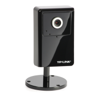
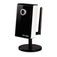
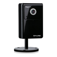
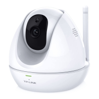
2.1 Front View
Focus Adjustment Ring: Adjust the focus ring to get a clear image.
Network LED Indicator: It lights up when the IP Camera is well connected to the network. It
flashes when there are data being transmitted.
Power LED Indicator: It lights up when the IP Camera is powered on.
Built-in Microphone: The location where the voice from your partner comes out.
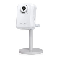
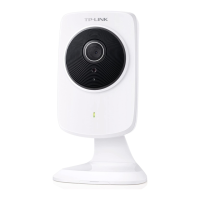
2.2 Bottom view
Power Connector: The power connector is where you connect the power adapter.
Reset: To successfully restore the camera to factory defaults, please keep the device powered on,
then press and hold the Reset Button for at least 10 seconds. The CPU of the camera starts to
work completely 1 minute after you release the Reset button.
Audio Out (Speaker): The Audio Out (Speaker) port is where the speaker is connected.
LAN (Network Connector): Through this port, you can connect the IP Camera to your computer
or the other Ethernet network devices.