JetStream L2/L2+ Managed Switch
21Connection
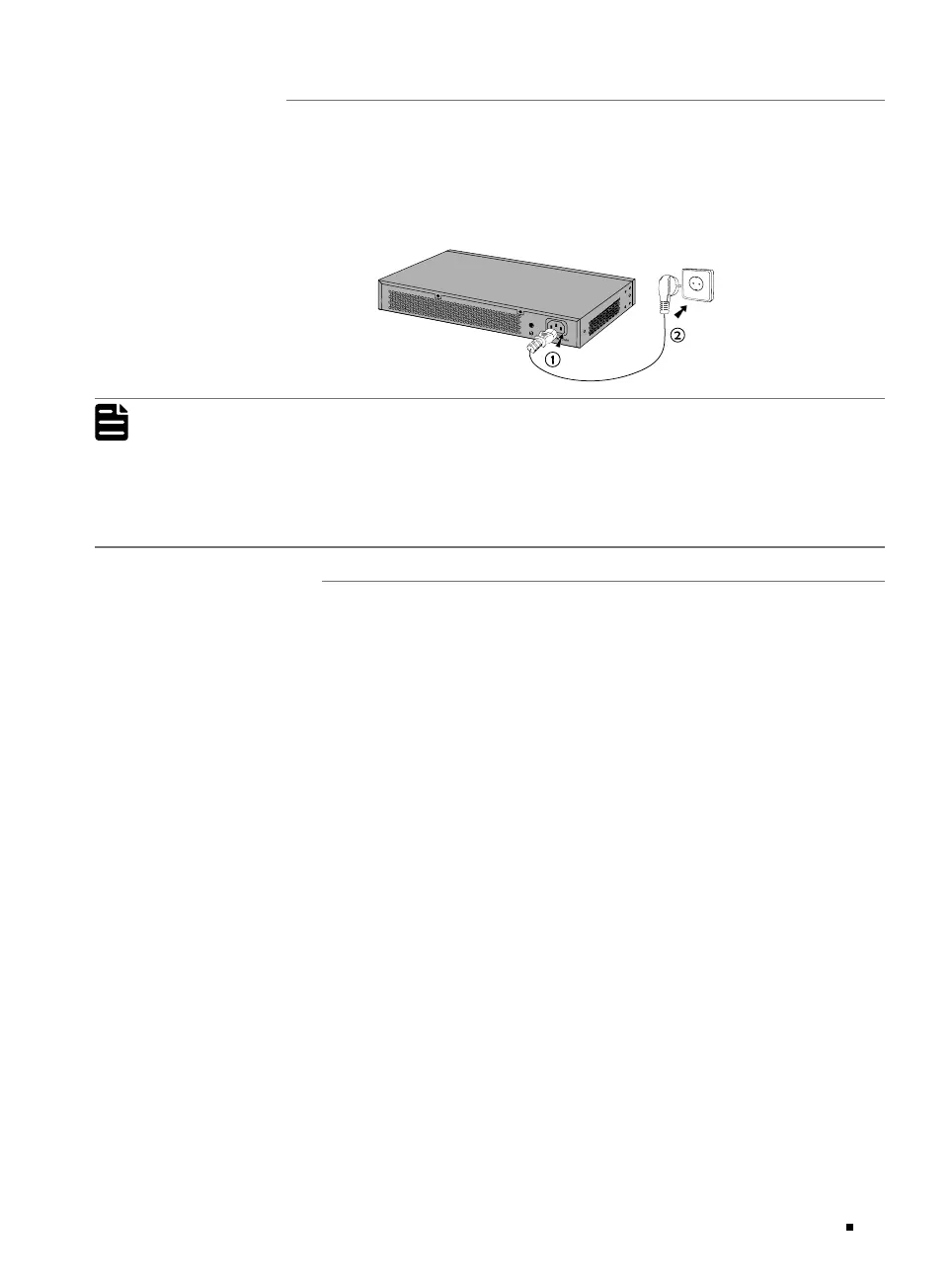
3.5 Power On
Plug the female connector of the provided power cord into the power socket of the device and plug
the positive connector into a power outlet as the following figure shows. Make sure that the voltage
of the power supply meets the requirement of the input voltage (100
-240 V~ 50/60 Hz).
Figure 3-5 Connecting to Power Supply
Note:
1. The gure is to illustrate the application and principle. The provided plug and the socket in
your region may dier from the gures above.
2. For TL-SG3428X-UPS, you can connect an external 12 V DC lead-acid battery as a redundant
power supply for the switch. The minimum required capacity is 4.5 AH. Battery is automatically
used to supply power when the AC power is turned off. When the AC power is working, it will
automatically charge the battery.
3.6 Initialization
After the device is powered on, it begins the Power-On Self-Test. A series of tests run automatically
to ensure the device functions properly. During this time, its LED indicators will respond in the
following order:
1. The PWR LED indicator lights on all the time. The SYS LED and the LED indicators of all the ports
keep off.
2. After about one minute, the SYS LED and LED indicators of all the ports will flash momentarily and
then turn off.
3. Several seconds later, the SYS LED indicator will flash, which represents a successful initialization.
 Loading...