Do you have a question about the TP-Link TL-SL1351 and is the answer not in the manual?
Details the high-performance, low-cost, and easy-to-use features of the Gigabit Uplink Unmanaged Switch.
Lists key technical specifications and capabilities of the switch, including IEEE standards and port types.
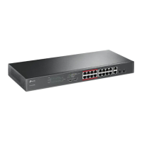
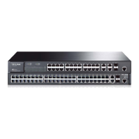
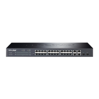
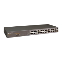
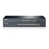
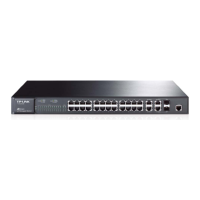
Describes the front panels of the TL-SL1226 and TL-SL1351 switches, including port layout and LEDs.
Details the rear panel components like the Grounding Terminal and Power Socket for the switches.
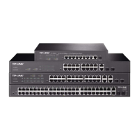
Lists the items included in the switch package, ensuring all components are present upon delivery.
Provides essential safety guidelines to prevent device damage and bodily injury during installation.
Outlines environmental conditions like temperature, humidity, clearness, and EMI for proper device operation.
Lists the necessary tools, such as screwdrivers and wrist wraps, for installing the network switch.
Provides step-by-step instructions for desktop and rack installation of the network switch.
Explains how to implement safe cabling practices, especially for outdoor installations, to prevent lightning damage.
Details methods for grounding the device, including connection to a grounding bar or via the power supply.
Explains the practice of connecting all earthed systems to create an equipotential zone to mitigate lightning strikes.
Describes the use of power and signal lightning arresters for surge protection against lightning.
Instructions for connecting network devices using RJ45 cables to the switch's Ethernet ports.
Guidance on connecting an SFP module to the switch's SFP port for extended network connectivity.
Checks to ensure proper installation, including ventilation, power supply, grounding, and network connectivity.
Steps for powering on the switch, connecting the power cord to the device and power outlet.
Describes the Power-On Self-Test process and how LED indicators respond during device initialization.
| Switching Capacity | 104 Gbps |
|---|---|
| Forwarding Rate | 77.4 Mpps |
| MAC Address Table | 16K |
| Jumbo Frame | 9 KB |
| Standards and Protocols | IEEE 802.3, IEEE 802.3u, IEEE 802.3x |
| Dimensions | 440 x 180 x 44 mm |
| Operating Temperature | 0°C to 40°C |
| Storage Temperature | -40°C to 70°C |
| Operating Humidity | 10%~90% non-condensing |
| Storage Humidity | 5%~90% non-condensing |
| Power Supply | 100-240V~, 50/60Hz |
| Mounting | Rack-mounted |
| VLAN | 802.1Q VLAN |
| IGMP Snooping | IGMP v1/v2/v3 snooping |
| Link Aggregation | Yes |
| Fan Quantity | 2 |