Do you have a question about the TP-Link TL-SX1008 and is the answer not in the manual?
Details the LEDs and ports on the front of the switch.
Details the Kensington security slot, power socket, and grounding terminal.
Provides instructions for setting up the switch on a desk.
Provides instructions for mounting the switch in a rack.
Details standards, protocols, interfaces, and environmental operating limits.
Covers essential safety measures, ESD prevention, and lightning protection.
Outlines optimal site conditions, temperature, humidity, and interference mitigation.
This document serves as an installation guide for the 8-Port 10G Multi-Gigabit Desktop/Rackmount Switch, providing comprehensive instructions for setup, usage, and maintenance to ensure optimal performance and longevity of the device.
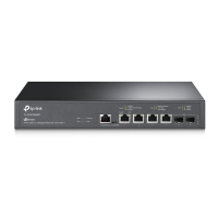
The 8-Port 10G Multi-Gigabit Desktop/Rackmount Switch is designed to facilitate high-speed network connectivity, offering eight RJ45 ports that support multiple gigabit speeds (100M/1G/2.5G/5G/10G). This versatility makes it suitable for a wide range of networking environments, from small offices to more demanding setups requiring robust data transfer capabilities. The switch supports auto-negotiation, allowing each port to automatically detect the link speed of a connected device and adjust for compatibility and optimal performance. It also features Auto MDI/MDIX, eliminating the need for crossover cables and simplifying network setup. The device operates on a store-and-forward transfer method, ensuring data integrity by checking for errors before forwarding packets. Its switching capacity of 160 Gbps enables efficient handling of high-bandwidth traffic across all ports. The switch also incorporates MAC Address Learning, which automatically builds and updates its MAC address table to efficiently direct traffic to the correct devices.
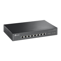
The front panel of the switch features LED indicators for power and individual port status. The Power LED indicates whether the device is on or off. Each port has two LEDs: a left LED for 10G/5G speeds and a right LED for 2.5G/1G/100M speeds. When a port LED is on, it signifies a connection to a device but no current activity. A flashing LED indicates that data is being transmitted or received. Specifically, for the left LED, green indicates 10 Gbps operation, and amber indicates 5 Gbps. For the right LED, green indicates 2.5 Gbps operation, and amber indicates 100/1000 Mbps. These visual cues provide immediate feedback on the network status and help in troubleshooting.
The rear panel includes the power socket for connecting the AC power cord, a grounding terminal for enhanced lightning protection, and a Kensington Security Slot. The Kensington Security Slot allows users to secure the device with a lock (not provided) to prevent theft, making it suitable for environments where physical security is a concern. The grounding terminal, while the switch already has built-in lightning protection, offers an additional layer of safety by allowing connection to a PE (Protecting Earth) cable or a dedicated ground cable, further safeguarding the device against electrical surges.
The switch offers flexible installation options, supporting both desktop and rackmount configurations. For desktop installation, the device can be placed on a flat surface, utilizing its feet for stability. For rackmount installation, the switch comes with rack-mounting brackets and screws, allowing it to be securely fitted into a standard server rack. When rack-mounting, it is crucial to leave 5 to 10 cm gaps around the devices for adequate air circulation and to avoid placing heavy objects on top of the switch. Devices should be mounted with their bottom facing downwards, and in sequence from bottom to top of the rack, ensuring sufficient clearance for heat dissipation.
Connecting the switch to your network is straightforward. The AC power cord connects the switch to an AC outlet, ensuring the voltage meets the 100-240 V ~ 50/60 Hz requirement. The Ethernet ports (1-8) on the front panel are used to connect network devices such as workstations, NAS/servers, gaming computers, 8K video devices, and 2.5G Wi-Fi 6 APs. The auto-negotiation feature of the ports simplifies connections, as they automatically adjust to the speed of the connected device.
The switch is designed to operate within specific environmental conditions. The recommended operating temperature is 0°C to 50°C (32°F to 122°F), and operating humidity is 10% to 90%RH non-condensing. Maintaining these conditions is vital for the device's performance and lifespan, as extreme temperatures or humidity can lead to insulation issues, electrical leakage, and accelerated aging of components.
Proper maintenance is essential for the longevity and reliable operation of the switch. Several safety precautions are outlined to prevent device damage and bodily injury. It is crucial to keep the power off during installation and maintenance. When handling the device, wearing an ESD-preventive wrist strap with good skin contact and proper grounding is recommended to prevent damage from electrostatic discharge. Only the power cord provided with the switch should be used, and the supply voltage must match the specifications on the rear panel.
Ensuring proper ventilation is a key maintenance aspect. The switch should be installed in a well-ventilated environment, and its ventilation holes must not be blocked. The cover of the switch should not be opened or removed by unauthorized personnel. Before cleaning, the power supply must be disconnected. The device should be cleaned with a dry cloth, avoiding water or any other liquid cleaning methods. The device should always be placed with its bottom surface downward.
Lightning protection measures are integrated into the switch, but additional steps can enhance safety. Ensuring that the rack and the device are well-earthed, and that the power socket has a good ground contact, is important. A reasonable cabling system should be maintained to avoid induced lightning. For outdoor wiring, using a signal SPD (Surge Protective Device) is recommended.
Maintaining a clean environment is also crucial. Dust accumulation can lead to static electricity and poor contact points. Regular dusting of the device and keeping the indoor air clean helps mitigate these risks. The device should be well-grounded to ensure static electricity is effectively transferred away.
To minimize electromagnetic interference, the switch should be powered by a supply that can effectively filter interference from the power grid. It should also be kept away from high-frequency and strong-current devices, such as radio transmitting stations. Using electromagnetic shielding when necessary can further reduce interference.
The installation site should be flat, stable, and sturdy enough to support the device's weight. Good ventilation in the equipment room is necessary, and the rack should be well-grounded. The device should be placed less than 1.5 meters away from the power socket for convenience and safety.
In summary, the 8-Port 10G Multi-Gigabit Desktop/Rackmount Switch is a high-performance networking device designed for ease of use and reliability. Adhering to the provided installation, usage, and maintenance guidelines will ensure its optimal operation and extended service life.
| Switch type | Unmanaged |
|---|---|
| Stackable | - |
| Form factor | 1U |
| Certification | CE, FCC , RoHS |
| Product color | Black |
| Rack mounting | Yes |
| Number of fans | 1 fan(s) |
| Installed SFP modules quantity | 0 |
| Basic switching RJ-45 Ethernet ports type | 10G Ethernet (100/1000/10000) |
| Basic switching RJ-45 Ethernet ports quantity | 8 |
| Networking standards | IEEE 802.3, IEEE 802.3ab, IEEE 802.3an, IEEE 802.3bz, IEEE 802.3p, IEEE 802.3x |
| Power source | AC |
| Input current | 0.8 A |
| AC input voltage | 100 - 240 V |
| AC input frequency | 50 - 60 Hz |
| Power consumption (max) | 28.4 W |
| Jumbo frames | 10000 |
| Forwarding rate | 119 Mpps |
| MAC address table | 32000 entries |
| Packet buffer memory | 16 MB |
| Storage temperature (T-T) | -40 - 70 °C |
| Operating temperature (T-T) | 0 - 50 °C |
| Storage relative humidity (H-H) | 5 - 90 % |
| Operating relative humidity (H-H) | 10 - 90 % |
| Package type | Box |
| Package depth | 400 mm |
| Package width | 250 mm |
| Package height | 80 mm |
| Package weight | 2070 g |
| Harmonized System (HS) code | 85176990 |
| Depth | 180 mm |
|---|---|
| Width | 294 mm |
| Height | 44 mm |