EasyManua.ls Logo

TP-Link VIGI C440I - User Manual

TP-Link VIGI C440I
2 pages
Print Icon
To Next Page IconTo Next Page
Loading...
3. Secure the Camera
Route the cable through the side outlet. Insert anchors into the holes,
use screws to ax the camera base, and attach the camera to it.
Appearance
*The camera’s standard power supply is 12V DC or PoE (802.3af/at). The power source should
comply with Power Source Class 2 ( PS2) or Limited Power Source(LPS) of IEC 62368-1.
*Some models do not have the power supply interface. You can check the detailed specications
on the product page at https://www.tp-link.com/.
Camera Base
Side Outlet
Lens
IR LED
1
2
Camera Body
3
Microphone
5
Camera
4
Power Supply Interface
(12V DC) *
9
7
RJ45 Ethernet Port
(supports PoE) *
8
6
5
2
3
1
4
6
8
9
7
3. Secure the Camera
Route the cable through the wall/ceiling. Insert anchors into the holes,
use screws to ax the camera base, and attach the camera to it.
Stick the mounting template to the desired mounting place. Drill
3 screw holes and 1 cable hole according to the template.
1. Drill Holes
2. Open the Camera Case
Align the notch of the camera body with any score on the camera
base, and use a screwdriver to gently pry open the camera case.
Quick Start Guide
Option 1: Cable through the wall/ceiling
Stick the mounting template to the desired mounting place. Drill
3 screw holes according to the template.
1. Drill Holes
2. Open the Camera Case
Align the notch of the camera body with any score on the camera
base, and use a screwdriver to gently pry open the camera case.
Option 2: Cable through the side outlet
1
Wall/Ceiling Mounting
4. Adjust the Surveillance Angle
Adjust the surveillance angle as needed. Make sure the lens is
positioned above the IR LED for normal viewing.
4. Adjust the Surveillance Angle
Adjust the surveillance angle as needed. Make sure the lens is
positioned above the IR LED for normal viewing.
Cable Hole
(For the cable through wall/ceiling)
Score of
camera base
Notch of
camera body
Score of
bottom case
Notch of
the shell
Score of
camera base
Notch of
camera body
Score of
bottom case
Notch of
the shell
Side Outlet
©2024 TP-Link 7106511161 REV1.20.0
IR Turret Network Camera
*Images may dier from actual products.
Tilt: 0° to 85°
Pan: 0° to 360°
Rotate: 0° to 360°
Mounting TemplateAnchors & Screws
Network Camera
Quick Start Guide
Quick
Start
Guide
Tilt: 0° to 85°
Pan: 0° to 360°
Rotate: 0° to 360°
Set up with videos:
Scan the QR code or visit
https://www.tp-link.com/support/setup-video/#vigi-network-camera
to search for the setup video of your product.
When installing with anchors
Φ = 6 mm (15/64 in.)
When installing with screws only
Φ = 3 mm (1/8 in.)
Appropriate drilling size (Φ)
Φ6 mm Φ3.5 mm
Question and Answer IconNeed help?

Do you have a question about the TP-Link VIGI C440I and is the answer not in the manual?

Overview

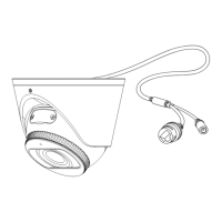
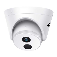
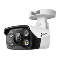
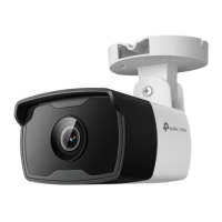
This document serves as a Quick Start Guide for the TP-Link VIGI IR Turret Network Camera, detailing its appearance, installation procedures, and methods for management and use with Network Video Recorders (NVRs).

The VIGI IR Turret Network Camera is designed for surveillance, offering live video monitoring and recording capabilities. Its primary function is to capture video footage, which can then be viewed and managed through various platforms, including VIGI NVRs, the VIGI Security Manager software, the TP-Link VIGI app, or a web browser. The camera supports Power over Ethernet (PoE) for simplified installation, allowing both power and data to be transmitted over a single Ethernet cable. It also includes an IR LED for night vision, ensuring continuous surveillance even in low-light conditions. A built-in microphone allows for audio capture alongside video.

Usage Features:

Installation:

The guide provides two main options for wall/ceiling mounting:

  1. Cable through the wall/ceiling: This method involves drilling a cable hole in addition to screw holes, allowing the Ethernet cable to be routed discreetly through the mounting surface.
  2. Cable through the side outlet: This option is suitable when routing the cable through the wall/ceiling is not preferred or feasible. The cable exits from a side outlet on the camera base.

For both installation methods, the process involves:

  • Drilling Holes: A mounting template is provided to accurately mark the positions for three screw holes and, if applicable, one cable hole. The appropriate drilling size for anchors (6 mm) or screws only (3 mm) is specified.
  • Opening the Camera Case: The camera case is designed to be opened by aligning a notch on the camera body with a score on the camera base and gently prying it open with a screwdriver. This step is necessary to access the mounting points and route the cable.
  • Securing the Camera: After routing the cable, anchors are inserted into the drilled holes (if needed), and the camera base is affixed to the mounting surface using screws. The camera body is then attached to the base.
  • Adjusting the Surveillance Angle: Once secured, the camera's surveillance angle can be adjusted. The pan (0° to 360°), tilt (0° to 85°), and rotation (0° to 360°) can be set to achieve the desired viewing area. It is crucial to ensure the lens is positioned above the IR LED for optimal night vision performance.

Connecting to an NVR:

The camera is designed to integrate seamlessly with NVRs for batch access and management. The guide primarily uses a VIGI NVR as an example, but also provides instructions for other NVR brands.

  • Hardware Connection: Cameras must be connected to the same network as the NVR, typically through a network device like a switch or router.
  • Power On: Cameras can be powered via PoE (802.3af/at) or an external 12V DC power supply.
  • Adding Cameras to VIGI NVR: On the VIGI NVR's Live View screen, users can right-click, select "Add Camera," and then choose their camera to add it directly. If Plug and Play is disabled on the NVR, a password must be created or a preset password used.
  • Adding Cameras to Other NVR Brands: For non-VIGI NVRs, cameras must first be activated by setting a password using the VIGI Security Manager, TP-Link VIGI app, or web management page, and then added according to the NVR's user manual.

Management Methods:

Beyond NVR integration, the camera offers several standalone management options:

  • VIGI Security Manager (Windows only): This software allows users to view live video and modify camera settings on a Windows computer. It automatically discovers cameras on the same network, enabling activation and addition through a password.
  • TP-Link VIGI App: Available on App Store and Google Play, this mobile app provides remote live video viewing, camera management, and instant alerts. Users log in with their TP-Link ID and follow in-app instructions to activate and add cameras.
  • Web Browser: For models supporting web management, users can access live video and modify settings via a web browser. This involves finding the camera's IP address on the router's client page, entering the IP address into a browser (e.g., https://192.168.0.60), selecting the Country/Region and Time Zone, and setting a password to activate the camera.

Maintenance Features:

Troubleshooting:

The guide includes a Frequently Asked Questions (FAQ) section to address common issues:

  • Cameras Not Discovered: If cameras are not discovered, users should refresh the discovery, ensure the camera is powered on, verify that the camera and NVR/computer are in the same subnet (using VIGI Security Manager to adjust network parameters if needed), or try to add the camera manually. For other NVR brands, activation via password (VIGI Security Manager or TP-Link VIGI app) is crucial.
  • Verifying Power On: To check if the camera is powered on, users can observe the IR LED, which should turn on for about 5 seconds upon power-up. If it's off, covering the lens for a few seconds should trigger the IR LED. Additionally, checking the Ethernet port LED status on the connected network device can confirm power and network connectivity.

Safety and Compliance:

The document emphasizes safety guidelines, including using only recommended chargers, avoiding damaged cables, and refraining from disassembling or modifying the device. It also states that the device complies with relevant EU and UK regulations regarding electromagnetic compatibility and electrical equipment safety.

For further technical support, replacement services, user guides, and more information, users are directed to the TP-Link support website or can scan a QR code.

TP-Link VIGI C440I Specifications

General IconGeneral
Image Sensor1/3" Progressive Scan CMOS
ApertureF1.6
Pan & TiltNo
Digital Zoom16x
Video CompressionH.265/H.264
Audio CommunicationTwo-way audio
Audio Input & OutputBuilt-in microphone and speaker
WirelessYes
Operating Temperature-30°C to 60°C (-22°F to 140°F)
Weatherproof RatingIP67
Night Vision30 m
Network Interface10/100Mbps Ethernet (RJ45)
Wireless Standards802.11 b/g/n
ProtocolsIPv4, IPv6
Power12V DC, PoE (802.3af)
Power ConsumptionMax. 6.1 W
StorageMicro SD card slot (up to 256GB)
Day/NightICR (IR cut filter)
Lens4mm fixed lens (2.8mm, 6mm optional)
Wireless SecurityWPA/WPA2-PSK

Related product manuals