Option 2: Route the cable through the side outlet. Insert anchors into the
holes and use screws to ax the camera base. Identify the groove and
alignment ridge on the camera. Begin by aligning the base's rim with the
camera's groove, attaching the ridge side rst for a correct t. Once aligned,
proceed to snap the rest of the camera onto the base to secure it.
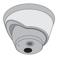
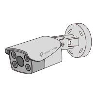
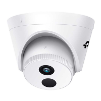
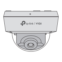
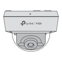
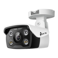
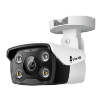
Appearance
Camera Base
Speaker
7
IR LED × 4
6
White LED × 4
5
Built-in Microphone
1
2
Reset
3
microSD Card Slot
Unfasten the two xed screws to
remove the cover. Insert a
microSD card for local storage.
Initialize the SD card via VIGI app
or other management tools
before recording videos.
Power Supply Interface
(12V DC) *
9
RJ45 Network Interface
(supports PoE) *
8
4
1
3
2
5
6
4
8
9
3. Secure the Camera
Option 1: Route the cable through the wall/ceiling. Insert anchors into the
holes and use screws to ax the camera base. Identify the groove and
alignment ridge on the camera. Begin by aligning the base's rim with the
camera's groove, attaching the ridge side rst for a correct t. Once aligned,
proceed to snap the rest of the camera onto the base to secure it.
Stick the mounting template to the desired mounting place. Drill 4 screw
holes and 1 cable hole (for the cable through wall/ceiling) according to the
template.
1. Drill Holes 2. Open the Camera Case
Use the L-shaped hex metal screwdriver to loosen the hex screw, and use a
screwdriver to gently pry open the camera case. .
Quick Start Guide
1
Wall/Ceiling Mounting
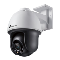
4. Adjust the Surveillance Angle
Use the L-shaped hex metal screwdriver to loosen the hex screw on the
base, and adjust the surveillance angle as needed.
Cable Hole
(For the cable through wall/ceiling)
Hex screw
Side Outlet
*Images may dier from actual products.
L-shaped Hex Metal
Screwdriver
Mounting TemplateAnchors & Screws
Network Camera
Quick Start Guide
Quick
Start
Guide
Unfasten the two xed screws to remove the
cover. Press for 5 seconds to reset the
camera to factory settings.
7
*
The camera’s standard power supply is 12V DC or PoE (802.3af/at). The power
source should comply with Power Source Class 2 ( PS2) or Limited Power
Source(LPS) of IEC 62368-1
.
©2023 TP-Link 7106510682 REV1.0.2
Φ6 mm Φ3.5 mm
Waterproof Cable
Attachments
When installing with anchors
Φ = 6 mm (15/64 in.)
When installing with screws only
Φ = 3 mm (1/8 in.)
Appropriate drilling size (Φ)
Waterproof Seal
5
6
Hex screw
Rim
Alignment Ridge
Rim
Alignment Ridge
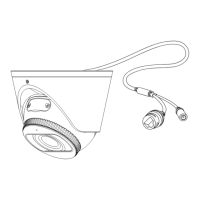
Installing Waterproof Cable Attachments
Install the waterproof cable attachments for the network interface if needed.
Note: Make sure each part is securely attached and the waterproof rings are ush to keep out water.
1. Route the network cable through the following components in order: x nut,
waterproof ring, and then the waterproof jacket.
2. Fix the O-ring to the network interface of the camera and connect the network
cables.
3. Attach the network interface with the waterproof jacket, then twist to lock.
4. Insert the waterproof ring into the waterproof jacket. Rotate the x nut to
secure it to the waterproof jacket.
Fix Nut
Waterproof
Ring
O-ring
Network
Interface
Waterproof
Jacket
Install the waterproof seal for the power connectors when using a power adapter
to power the camera.
Install Waterproof Seal for Power Connectors
Male Power Connector Waterproof Seal
Female Power Connector
5. Tighten the Hex Screw
Tighten the hex screw to secure the camera to the camera base. Hold the
camera and ensure the camera and base are as close together as possible
when tightening.
Tilt: 0° to 85°
Pan: 0° to 360°
Rotate: 0° to 360°