EasyManua.ls Logo

TP-Link VIGI C240 User Manual

TP-Link VIGI C240
2 pages
To Next Page IconTo Next Page
Page #1 background imageLoading...
Page #1 background image
Appearance
Power Supply Interface
(12V DC)
RJ45 Ethernet Port
(supports PoE)
Micro SD Slot*
IR LED
Top Cover
Side Screws
Microphone
Reset Button*
Press for 5 seconds to reset the
camera to factory settings.
Loosen to remove the top cover.
Micro SD Reset
Quick Start Guide
*Images may dier from actual products.
Package Contents
Network Camera
Quick Start Guide
Anchors & Screws
Quick
Start
Guide
Make sure your power supply matches your camera. The
camera’s standard power supply is 12V DC or PoE
(802.3af/at). The power source should comply with Power
Source Class 2 ( PS2) or Limited Power Source(LPS) of IEC
62368-1.
• Make sure that the wall is strong enough to withstand 4
times the weight of the camera and mounting bracket.
• If you are uncertain or uncomfortable performing the
installation, consult a qualied electrician.
Safety First:
Mounting Template
2. Decide how to route the cable through the ceiling/wall. 4. Rotate the lens base or the dome to adjust the angle of the
lens as desired. Tighten the side screws to secure the cover.
1. Loosen the screws on the side of the camera to remove
the top cover.
3. Stick the mounting template to the desired mounting place,
and mount the camera. Pay attention to the cable direction.
Dome Network Camera
Mounting Template
Anchor
Reinstall the top cover
Adjust lens angle
Mount the camera
Remove the top cover
Ceiling or Wall
Route the cable through the
bottom of the camera
Knock out the cable hole on the side
and route the cable from the side
Self-tapping Screw
*Some models do not have the SD slot and reset button. You can check the detailed
specications on the product page at https://www.tp-link.com/.
Camera
Ceiling or Wall
Waterproof Cable
Attachments
Installing Waterproof Cable Attachments
Install the waterproof cable attachments for the network interface when the
camera is installed outdoors.
Note: Make sure each part is securely attached and the waterproof rings are
ush to keep out water.
Done! The network interface is now waterproof.
Fix Nut
Waterproof
Ring
O-ring
Network
Interface
Waterproof
Jacket
1. Route the network cable through the following components in order: x
nut, waterproof ring, and then the waterproof jacket.
2. Fix the O-ring to the network interface of the camera and connect the
network cables.
3. Attach the network interface with the waterproof jacket, then twist to
lock.
4. Insert the waterproof ring into the waterproof jacket. Rotate the x nut
to secure it to the waterproof jacket.
White LED
Question and Answer IconNeed help?

Do you have a question about the TP-Link VIGI C240 and is the answer not in the manual?

TP-Link VIGI C240 Specifications

General IconGeneral
Image Sensor1/2.7" CMOS
ApertureF2.0
Night VisionUp to 30 m
Video CompressionH.265/H.264
Frame Rate30 fps
Ethernet10/100 Mbps
Weather ResistanceIP67
Audio CompressionG.711
ProtocolsTCP/IP, UDP, HTTP, HTTPS, RTSP, ONVIF, DHCP
Wireless Standards802.11b/g/n
Operating Temperature-30°C to 60°C
Power SupplyPoE (802.3af)
StorageMicroSD card slot
Power ConsumptionMax 5.5W

Summary

Safety First

Camera Components Overview

Microphone, RJ45 Port, Power Interface

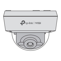
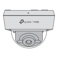
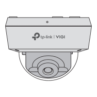
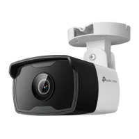
Identifies key audio, network, and power connection ports on the camera.

Micro SD Slot and Reset Button

Locates the memory card slot and the button for factory reset.

IR LED and White LED

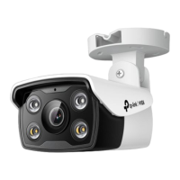
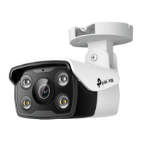
Indicates the camera's infrared and white light emitting diodes.

Top and Side Covers

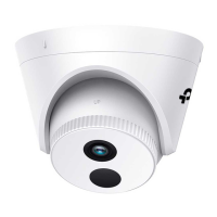
Details the camera's top cover and side screws for access.

Mounting the Camera

Remove Top Cover

Loosen side screws to detach the camera's top cover for installation.

Cable Routing Options

Decide how to route the network cable through the ceiling or wall.

Mounting Procedure

Use the template to mount the camera, paying attention to cable direction.

Adjusting and Securing

Rotate the lens base or dome to adjust the angle, then tighten screws.

Waterproof Cable Attachment Installation

Prepare Cable Components

Route the network cable through the fix nut, waterproof ring, and waterproof jacket.

Attach O-ring and Connect Cable

Fix the O-ring to the camera's network interface and connect network cables.

Attach Waterproof Jacket

Attach the network interface with the waterproof jacket and twist to lock.

Insert O-ring and Secure Fix Nut

Insert the O-ring into the jacket and rotate the fix nut to secure it.

Using Your Camera with an NVR

Connect Hardware

Connect cameras to the same network as your NVR.

Power On Cameras

Power on your cameras using PoE or an external power supply.

Add Cameras to NVR

Add cameras to the NVR via the Live View screen by clicking 'Add Camera'.

Using Cameras with Other NVR Brands

Power On and Connect

Power on your cameras and connect them to the network.

Activate Camera

Activate the camera using VIGI Security Manager or TP-Link VIGI app.

Add Cameras to NVR

Refer to the NVR's User Manual to add cameras.

More Camera Management Methods

VIGI Security Manager

Manage cameras via a Windows application for live video and settings.

TP-Link VIGI App

Remotely view live video, manage cameras, and receive alerts via the mobile app.

Web Browser Access

Access and modify camera settings and view live video through a web browser.

Frequently Asked Questions

No Cameras Discovered

Troubleshooting steps for when cameras are not discovered by the NVR or software.

Camera Power Status Check

Methods to confirm if the camera is receiving power.

Related product manuals