INSTALLATION INSTRUCTIONS | PAGE 13IN-0050
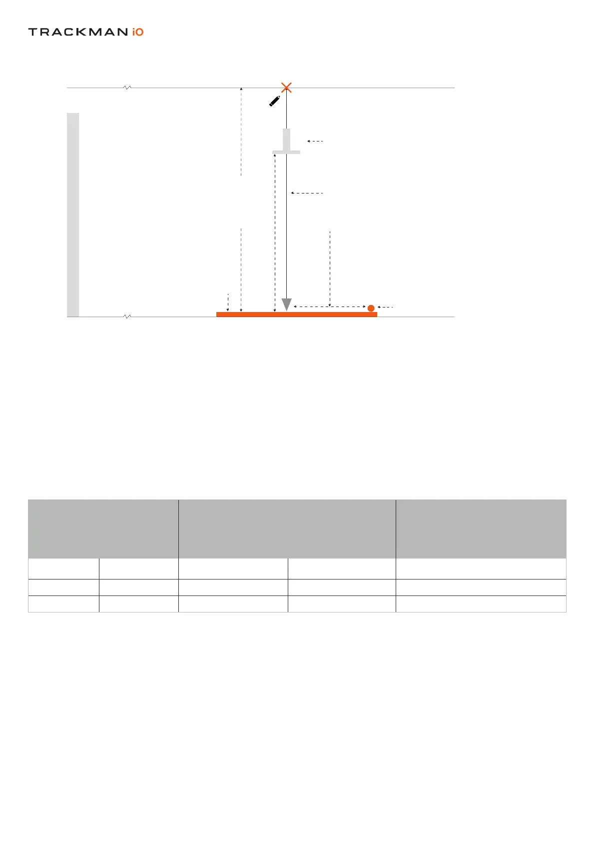
PositionthebaseoftheVESA onthesothatthecenteroftheadjustablepole
extendsfromthecenteroftheXyoumarkedinStep4.AttachthebaseoftheVESA tothe
followingmanufacturer’sinstructions.
AdjustthepoleontheVESA sothatthebracketthatattachestoyourissettothe
recommendedmountingheightof295cm/9’8”asshowninTable2(seeNOTEbelow).
Table2showstherelationbetweenthemountingheightandtheproperpositionoftheonthe
.Pleasenotethatifthemountingheightishigherorlowerthanrecommended(butstillwithin
theguidelines),youmayneedtoadjustthepositionoftherslightly.Ifyourisnotinstalled
accordingtotheguidelinesinTable2,itmaynotfunctionproperly.
HITTING SURFACE
>305 CM / 10’0”
HITTING SCREEN
VESA 100X100 MOUNT
CEILING
DISTANCE FROM CENTER
OFF TEE MARKER
TO CENTER OF VESA
100X100 MOUNT
PREFERRED TEE MARKER
POSITION
PLUMB LINE
SIDE VIEW
HITTING SCREEN
HITTING SCREEN
HITTING SURFACE
CEILING SURFACE
TEE MARKER
IN THE CENTER OF
THE BEAM
CALIBRATION TARGET
SIDE VIEW
295CM/9’8” RECOMMENDED
Table 2 Distance from Tee Marker to center of VESA Mount
Distancefromcenterof Mountingheight(cm)/(ft/in) Comments
tocenterofVESA
cm ft/in cm ft/in
105 3’5” 305 10’0 Max.
98.5 3’3” 285 9’4” Min.