19
8.1 Considerations
Important: Due to the unique design of this unit,
which allows the electrical wiring to be routed within
the insulation, do not screw, cut, or otherwise puncture
the unit cabinet in any location other than the ones
illustrated in this Installer Guide or in an approved ac-
cessory’s Installer Guide.
Important: Make certain that the unit has been in-
stalled in a level position to ensure proper draining.
Important: Under no conditions should metal strap-
ping be attached to the unit to be used as support
mechanisms for carrying or suspension purposes.
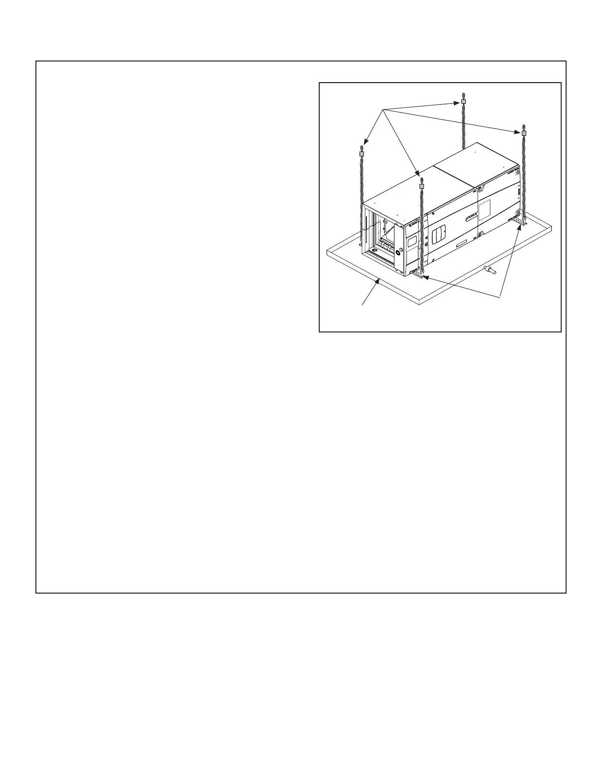
Field Supplied
Isolators
Auxiliary Drain
Pan
Bottom Support
Near Both Ends
Section 8. Setting the Unit - Horizontal Installation
Important: For the 5 ton air handler models
GAM5B0C60M51SB and GAM5B0C60M51EA, tap
5 should not be used in the downflow or horizontal
orientations. Using Tap 5 could result in water
blowing off the coil.
Note: BAYHHKIT001A Hanging Bracket Kit may be
ordered separately.
Important: The BAYHHKIT001A may not be used
if the cabinet has been altered per Installer Guide
18-GJ58D1-1.
STEP 1 - Support the unit from the bottom (near both
ends). The service access must remain unobstructed.
Important: The unit can only be supported from the
bottom unless using kit BAYHHKIT001A. Do not drill
or screw supports into any area of the cabinet.
Note: Do not allow the unit to be used as strain relief.
• Approved bottom support methods are rails, u-chan-
nels (Unistrut®), or other load bearing materials.
• The unit must be isolated carefully to prevent sound
transmission. Field supplied vibration isolators are
recommended.
STEP 2 - Install an auxiliary drain pan under the
horizontal air handler to prevent possible damage to
ceilings.
• Isolate the auxiliary drain pan from the unit and from
the structure.
• Connect the auxiliary drain pan to a separate drain
line and terminate according to local codes.