4 UNT-PRC002-GB
Technical Data
FWD 08 12 20 30 45
Power supply (V/Ph/Hz) 230/1/50
Capacities
Cooling capacity on water (1) (kW) 5,2 8,3 15 18,8 30,1
Heating capacity on water (2) (kW) 6,3 11,9 18,9 20,9 38,2
Fan motor (type) 2 x direct drive centrifugal
Fan power input (3) (kW) 0,23 0,46 0,65 1,04 1,51
Current amps (3) (A) 1,1 2,2 3,1 4,7 5,5
Start-up amps (A) 3,2 5,5 9,3 14,1 16,5
Air flow
minimum (m
3
/h) 490 980 1400 1800 2700
nominal (m
3
/h) 820 1650 2300 3000 4500
maximum (m
3
/h) 980 1970 2600 3600 5400
Main coil
Water entering/leaving connections (type) ISO R7 rotating female
(Dia) 3/4" 3/4" 1 1/2" 1 1/2" 1 1/2"
Electric heater (accessory for blower only)
Electric power supply (V/Ph/Hz) 230/1/50 230/1/50 or 400/3/50 400/3/50 400/3/50 400/3/50
Heating capacity (kW) 2/4 8 10 12 12
Hot water coil (accessory for blower only)
Heating capacity (4) (kW) 6,3 12 17,4 22,4 34,5
G2 filter (filter box accessory)
Quantity 2 2 2 2 2
Dimensions ( LxWxth) (mm) 386x221x8 486x271x8 586x321x8 586*421*8 586*621*8
G4 filter (filter box accessory)
Quantity - 2 2 2 2
Dimensions ( LxWxth) (mm) - 486x264x48 586x314x48 586*414*48 586*614*48
Condensate pump (accessory) (type) Centrifugal
Water flow - lift height (l/h - mm) 24 - 500
Not available for FWD30 and FWD45
Sound level (L/M/H speed)
Sound pressure level (5) (dB(A)) 36/40/43 38/41/44 46/50/53 47/52/57 47/52/58
Sound power level (5) (dB(A)) 46/50/53 48/51/54 56/60/63 57/62/67 57/62/68
Unit dimensions
Width x Depth (mm) 890 x 600 1090 x 710 1290 x 820 1290 x 970 1290 x 1090
Height (mm) 250 300 350 450 650
Shipped unit dimensions
Width x Depth (mm) 933 x 644 1133 x 754 1333 x 864 1333 x 1008 1333*1133
Height (mm) 260 310 360 460 660
Weight (kg) 32 46 61 76 118
Colour galvanised steel
Recommended fuse size
Unit alone (aM/gI) (A) 8/16 8/16 8/16 8/25 8/25
Unit with electric heater (gI) (A) 16 (2kW),25 (4kW) 40 (230V),3*16 (400V) 3*20 3*25 3*25
(1) Conditions: Water entering/leaving temperature: 7/12 °C, Air inlet temperature 27/19°C DB/WB - Nominal air flow
(2) Conditions: Water entering/leaving temperature: 50/45 °C, Air inlet temperature 20°C DB - Nominal air flow
(3) At high speed with nominal air flow.
(4) Water entering/leaving temperature 90/70 °C, air inlet temperature 20 °C DB, Nominal air flow.
(5) A rectangular glass wool duct 1m50 long is placed on the blower.The measurement is taken in the room containing the blower unit.
Heat exchanger operating limits:
FWD:
*water temperature: max 100° C
*absolute service pressure: min 1 bar/max 11 bars
Accessories - Hot water coil:
*water temperature: min. +2° C/max. 100° C
*absolute service pressure: min 1 bar/max 11 bars
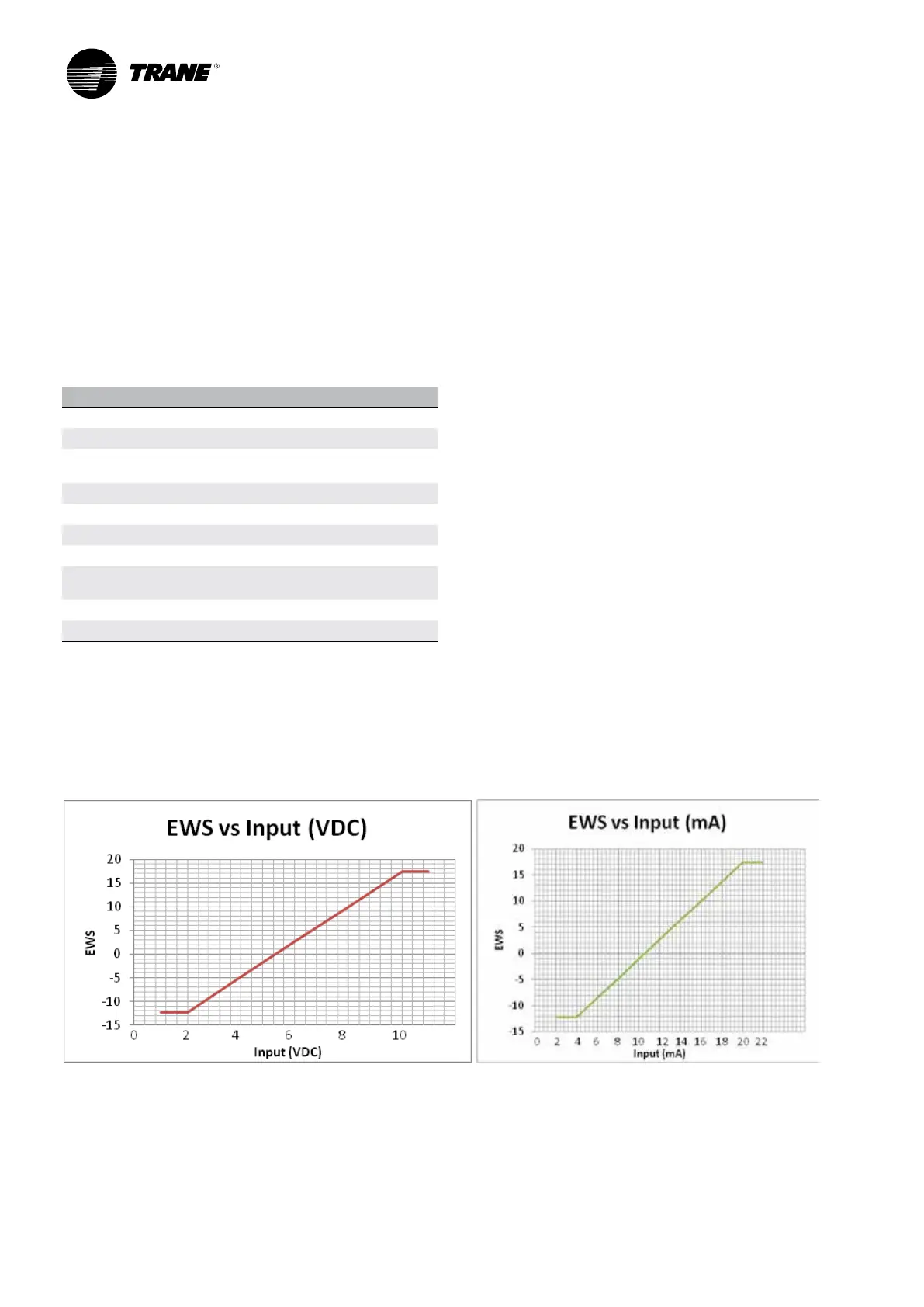
The UC800 provides inputs that accept either 4-20 mA or 2-10 VDC signals to set the ECHWS. This is not a reset
function. The input defines the setpoint. This input is primarily used with generic BAS (building automation
systems).
When the unit is in cooling mode, the external water setpoint (EWS) corresponds to the chilled water setpoint. When
the unit is in heating mode, the external water setpoint (EWS) corresponds to the hot water setpoint. The external
water setpoint shall have a configurable minimum and maximum set for cooling, and another one for heating.
2-10 VDC and 4-20 mA shall each correspond to an EWS range with a configurable minimum and maximum EWS.
If the ECHWS input develops an open or short, the LLID will report either a very high or very low value back to the
main processor. This will generate an informational diagnostic and the unit will default to using the Front Panel
(TD7) Chilled Water Setpoint.
Tracer TU Service Tool is used to set the input signal type from the factory default of 2-10 VDC to that of 4-20 mA.
Tracer TU is also used to install or remove, enable or disable the External Chilled Water Setpoint.