23
11UNT-PRC002-GB
Sound power levels
Discharge
Measurement conditions:
Measurements taken in a room adjacent to the room containing the FWD, at the outlet of the rectangular duct (1.5 m
long) fixed to its discharge opening.
Fan Power level in dB(A), per Hz frequency band Overall power
Unit speed 125 250 500 1000 2000 4000 8000 dB(A)
1 55 50 42 37 37 31 30 46
FWD 08 2 57 54 47 40 30 38 40 50
3 58 57 50 42 32 40 43 53
1 57 51 45 42 34 33 28 48
FWD 10 2 58 54 48 45 38 39 35 51
3 60 58 50 48 40 42 39 54
1 57 51 45 42 34 33 28 48
FWD 12 2 58 54 48 45 38 39 35 51
3 60 58 50 48 40 42 39 54
1 56 62 50 48 39 38 36 56
FWD 14 2 61 66 55 53 47 46 45 60
3 63 69 58 56 50 50 49 63
1 57 63 51 49 40 39 37 57
FWD 20 2 61 66 55 53 47 46 45 60
3 63 69 58 56 50 50 49 63
Intake
Measurement conditions:
Measurements taken at the horizontal air intake.
Fan Power level in dB(A), per Hz frequency band Overall power
Unit speed 125 250 500 1000 2000 4000 8000 dB(A)
1 56 55 55 53 46 45 42 57
FWD 08 2 63 62 60 60 53 53 53 64
3 66 65 63 62 56 55 57 67
1 62 58 55 58 51 48 44 61
FWD 10 2 66 63 60 62 56 55 52 66
3 70 67 63 65 59 59 57 69
1 62 58 55 58 51 48 44 61
FWD 12 2 66 63 60 62 56 55 52 66
3 70 67 63 65 59 59 57 69
1 66 65 65 65 57 50 46 68
FWD 14 2 73 72 69 71 64 59 57 74
3 78 76 73 75 69 64 63 78
1 68 72 64 64 56 52 50 69
FWD 20 2 76 76 68 71 65 61 61 75
3 78 79 71 74 69 66 66 78
CG-SVU010C-GB
Wiring and Port Descriptions for MODBUS, BACnet and LonTalk
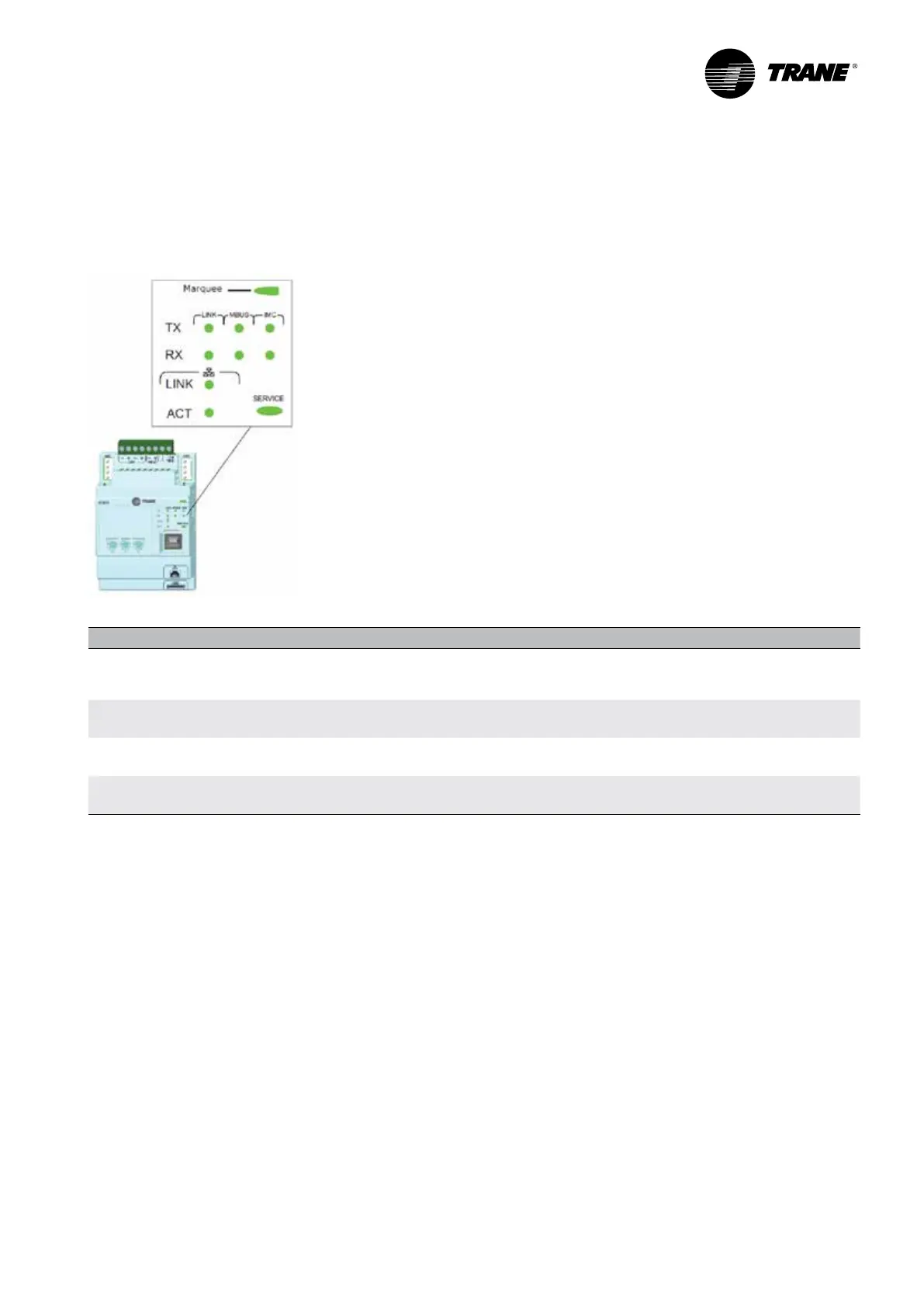
LED Description and Operation
There are 10 LEDs on the front of the UC800. Figure 2 shows the locations of each LED and Table 5 describes their
behavior in specific instances.
Figure 2 –
LED locations
Table 5 –
LED behavior
LED UC800 Status
Marquee
LED
Powered. If the Marquee LED is green solid, the UC 800 is powered and no problem exist
Low power or malfunction. If the Marquee LED is red solid, the UC800 is powered, but there are problems
present Alarm. The Marquee LED blinks Ren when an alarm exists
LINK,
MBUS, IMC
The TX LED blinks green at the data transfer rate when the UC800 transfers data to other devices on the link
The Rx LED blinks yellow at the data transfer rate when UC800 receives data from other devices on the link
Ethernet
Link
The LINK LED is solid green if the Ethernet links is connected and connecting
The ACT LED blinds yellow at the data transfer rate when data ow is active on the link
Service
The Service LED is solid green when pressed.
For qualied service technicians only. Do not use
NOTICE:
Electrical Noise!
Maintain at least 6 inches between low-voltage (<30V) and high voltage circuits. Failure to do so could result in
electrical noise that could distort the signals carried by the low-voltage wiring, including IPC.