6
4 UNT-PRC002-GB
Technical Data
FWD 08 12 20 30 45
Power supply (V/Ph/Hz) 230/1/50
Capacities
Cooling capacity on water (1) (kW) 5,2 8,3 15 18,8 30,1
Heating capacity on water (2) (kW) 6,3 11,9 18,9 20,9 38,2
Fan motor (type) 2 x direct drive centrifugal
Fan power input (3) (kW) 0,23 0,46 0,65 1,04 1,51
Current amps (3) (A) 1,1 2,2 3,1 4,7 5,5
Start-up amps (A) 3,2 5,5 9,3 14,1 16,5
Air flow
minimum (m
3
/h) 490 980 1400 1800 2700
nominal (m
3
/h) 820 1650 2300 3000 4500
maximum (m
3
/h) 980 1970 2600 3600 5400
Main coil
Water entering/leaving connections (type) ISO R7 rotating female
(Dia) 3/4" 3/4" 1 1/2" 1 1/2" 1 1/2"
Electric heater (accessory for blower only)
Electric power supply (V/Ph/Hz) 230/1/50 230/1/50 or 400/3/50 400/3/50 400/3/50 400/3/50
Heating capacity (kW) 2/4 8 10 12 12
Hot water coil (accessory for blower only)
Heating capacity (4) (kW) 6,3 12 17,4 22,4 34,5
G2 filter (filter box accessory)
Quantity 2 2 2 2 2
Dimensions ( LxWxth) (mm) 386x221x8 486x271x8 586x321x8 586*421*8 586*621*8
G4 filter (filter box accessory)
Quantity - 2 2 2 2
Dimensions ( LxWxth) (mm) - 486x264x48 586x314x48 586*414*48 586*614*48
Condensate pump (accessory) (type) Centrifugal
Water flow - lift height (l/h - mm) 24 - 500
Not available for FWD30 and FWD45
Sound level (L/M/H speed)
Sound pressure level (5) (dB(A)) 36/40/43 38/41/44 46/50/53 47/52/57 47/52/58
Sound power level (5) (dB(A)) 46/50/53 48/51/54 56/60/63 57/62/67 57/62/68
Unit dimensions
Width x Depth (mm) 890 x 600 1090 x 710 1290 x 820 1290 x 970 1290 x 1090
Height (mm) 250 300 350 450 650
Shipped unit dimensions
Width x Depth (mm) 933 x 644 1133 x 754 1333 x 864 1333 x 1008 1333*1133
Height (mm) 260 310 360 460 660
Weight (kg) 32 46 61 76 118
Colour galvanised steel
Recommended fuse size
Unit alone (aM/gI) (A) 8/16 8/16 8/16 8/25 8/25
Unit with electric heater (gI) (A) 16 (2kW),25 (4kW) 40 (230V),3*16 (400V) 3*20 3*25 3*25
(1) Conditions: Water entering/leaving temperature: 7/12 °C, Air inlet temperature 27/19°C DB/WB - Nominal air flow
(2) Conditions: Water entering/leaving temperature: 50/45 °C, Air inlet temperature 20°C DB - Nominal air flow
(3) At high speed with nominal air flow.
(4) Water entering/leaving temperature 90/70 °C, air inlet temperature 20 °C DB, Nominal air flow.
(5) A rectangular glass wool duct 1m50 long is placed on the blower.The measurement is taken in the room containing the blower unit.
Heat exchanger operating limits:
FWD:
*water temperature: max 100° C
*absolute service pressure: min 1 bar/max 11 bars
Accessories - Hot water coil:
*water temperature: min. +2° C/max. 100° C
*absolute service pressure: min 1 bar/max 11 bars
CG-SVU010C-GB
Installer-Supplied Components
Customer wiring interface connections are shown in the electrical schematics and connection diagrams that are
shipped with the unit. The installer must provide the following components if not ordered with the unit:
• Power supply wiring (in conduit) for all field-wired connections.
• All control (interconnecting) wiring (in conduit) for field supplied devices.
• Fused-disconnect switches or circuit breakers.
Interconnecting Wiring
Chilled Water Pump Control
NOTICE:
Equipment Damage!
If the microprocessor calls for a pump to start and water does not flow, the evaporator may be damaged
catastrophically. It is the responsibility of the installing contractor and/or the customer to ensure that a pump will
always be running when called upon by the chiller controls.
An evaporator water pump output relay closes when the chiller is given a signal to go into the Auto mode
of operation from any source. The contact is opened to turn off the pump in the event of most machine level
diagnostics to prevent pump overheat.
The relay output is required to operate the Evaporator Water Pump (EWP) contactor. Contacts should be compatible
with 115/240 VAC control circuit. Normally, the EWP relay follows the AUTO mode of the chiller. Whenever the chiller
has no diagnostics and is in the AUTO mode, regardless of where the auto command is coming from, the normally
open relay is energized. When the chiller exits the AUTO mode, the relay is timed to open in an adjustable (using TU)
0 to 30 minutes.
The non-AUTO modes, in which the pump is stopped, includes Reset, Stop, External Stop, Remote Display Stop,
Stopped by Tracer, Start Inhibited by Low Ambient Temp, and Ice Making complete.
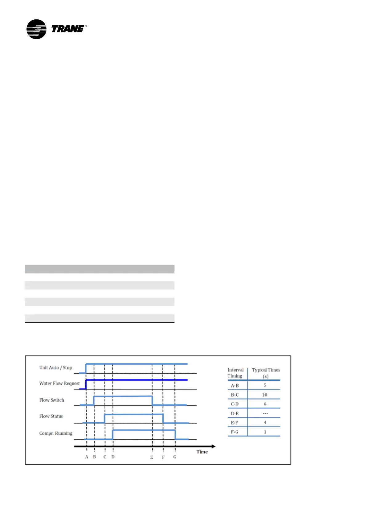
Table 1 –
Pump relay operation
Chiller Mode Relay Operation
Auto Instant Close
Ice Making Instant Close
Tracer Override Close
Stop Timed Open
Ice Complete Instant Open
Diagnostics Instant Open
When going from Stop to Auto, the Evaporator Water Pump relay is energized. Water flow switch is activating, and
flow status information back after 15 seconds.
Installer-Supplied Components / Interconnecting Wiring