13
11UNT-PRC002-GB
Sound power levels
Discharge
Measurement conditions:
Measurements taken in a room adjacent to the room containing the FWD, at the outlet of the rectangular duct (1.5 m
long) fixed to its discharge opening.
Fan Power level in dB(A), per Hz frequency band Overall power
Unit speed 125 250 500 1000 2000 4000 8000 dB(A)
1 55 50 42 37 37 31 30 46
FWD 08 2 57 54 47 40 30 38 40 50
3 58 57 50 42 32 40 43 53
1 57 51 45 42 34 33 28 48
FWD 10 2 58 54 48 45 38 39 35 51
3 60 58 50 48 40 42 39 54
1 57 51 45 42 34 33 28 48
FWD 12 2 58 54 48 45 38 39 35 51
3 60 58 50 48 40 42 39 54
1 56 62 50 48 39 38 36 56
FWD 14 2 61 66 55 53 47 46 45 60
3 63 69 58 56 50 50 49 63
1 57 63 51 49 40 39 37 57
FWD 20 2 61 66 55 53 47 46 45 60
3 63 69 58 56 50 50 49 63
Intake
Measurement conditions:
Measurements taken at the horizontal air intake.
Fan Power level in dB(A), per Hz frequency band Overall power
Unit speed 125 250 500 1000 2000 4000 8000 dB(A)
1 56 55 55 53 46 45 42 57
FWD 08 2 63 62 60 60 53 53 53 64
3 66 65 63 62 56 55 57 67
1 62 58 55 58 51 48 44 61
FWD 10 2 66 63 60 62 56 55 52 66
3 70 67 63 65 59 59 57 69
1 62 58 55 58 51 48 44 61
FWD 12 2 66 63 60 62 56 55 52 66
3 70 67 63 65 59 59 57 69
1 66 65 65 65 57 50 46 68
FWD 14 2 73 72 69 71 64 59 57 74
3 78 76 73 75 69 64 63 78
1 68 72 64 64 56 52 50 69
FWD 20 2 76 76 68 71 65 61 61 75
3 78 79 71 74 69 66 66 78
CG-SVU010C-GB
External setpoints & capacity outputs (Optional)
External Demand Limit Setpoint (EDLS)
Like previously, either 2-10 VDC (default) or 4-20 mA inputs are available as option to set External Demand Limit
Setpoint. The Demand Limit Setting can also be set via the Tracer TD7 or through digital communication with Tracer
(Comm4). The arbitration of the various sources of demand limit is described in the flow charts at the end of this
section. The External Demand Limit Setpoint may be changed from a remote location by hooking up the analog input
signal to the 1A19 LLID terminals 5 and 6. Refer to the following paragraph on Analog Input Signal Wiring Details.
Functional Description
The UCM shall accept either a 2-10 VDC or 4-20 mA analog input suitable for customer connection to set the unit
external demand limit set point (EDLS).
If the EDLS input develops an open or short, the LLID will report either a very high or very low value back to the
main processor. This will generate an informational diagnostic and the unit will default to using the Front Panel
(Tracer TD7) Demand Limit Setpoint.
The Tracer™ TU Service Tool must be used to set the input signal type from the factory default of 2-10 VDC to that of
4-20 mA current. Tracer TU must be also be used to install or remove the External Current Limit Setpoint Option for
field installation, or can be used to enable or disable the feature (if installed).
If the Demand Limit Setpoint is set at 100%, the controller will allow every available compressors on the unit to run.
Number of compressors allowed = round ( Demand Limit Setpoint * Number of Compressors on Unit ).
The minimum active value is 100% / Number of Compressors on Unit.
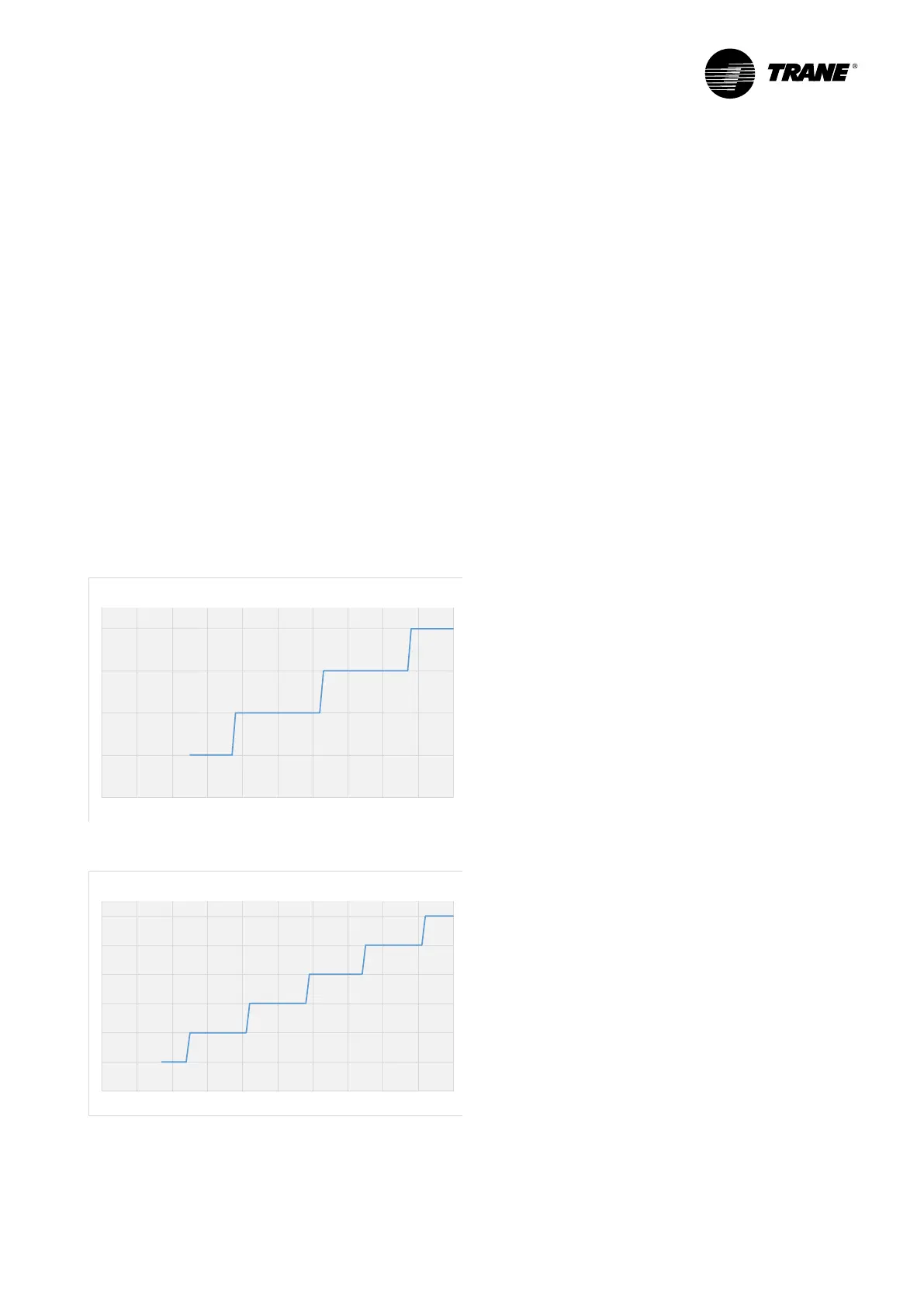
Current limit Setpoint via 2-10 VDC signal
0
1
2
3
4
0 10 20 30 40 50 60 70 80 90 100
Active Demand Limit Setpoint (%)
Number of allowed compressors
(4 compressors unit)
Current limit Setpoint via 4-20 mA signal
0
1
2
3
4
5
6
0 10 20 30 40 50 60 70 80 90 100
Active Demand Limit Setpoint (%)
Number of allowed compressors
(6 compressors unit)