EasyManua.ls Logo

Trane 13.4 SEER2 J4PH4 Series User Manual

Trane 13.4 SEER2 J4PH4 Series
29 pages
To Next Page IconTo Next Page
Page #1 background imageLoading...
Page #1 background image
INSTALLATION INSTRUCTIONS
Thank you very much for purchasing our product,
Before using your unit , please read this manual carefully and keep it for future reference.
The figure shown in this manual is for reference only and may be slightly different from the actual product.
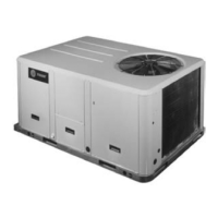
PACKAGED HEAT PUMP
FEATURING R-410A
13.4 SEER2 J4PH4 SERIES - (2-5Tons)

Questions and Answers:

Trane 13.4 SEER2 J4PH4 Series Specifications

General IconGeneral
BrandTrane
Model13.4 SEER2 J4PH4 Series
CategoryHeat Pump
LanguageEnglish

Summary

SAFETY

1.1 Inspection

Check the unit for possible shipping damage upon receipt.

1.2 Limitations

Refer to figures and tables for unit data; adhere to local codes for added components.

INSTALLATION

2.1 Pre-Installation

Check compliance with national/local codes and ensure proper site preparation.

2.2 Clearance

Maintain specified clearances for proper operation and servicing.

2.3 Rigging and Handing

Exercise care when moving and lifting the unit, using provided lifting points.

CONDENSATE DRAIN CONNECTION

4.1 Install Drain Pipe

Connect the drain pipe using the provided fitting, ensuring no blockages.

ELECTRICAL WIRING

6.1 Power Wiring

Ensure proper electrical power is available and follow wiring diagrams.

6.2 Grounding

The unit must be permanently grounded for safety.

6.3 Control Wiring

Follow guidelines for low voltage control wiring separation and thermostat installation.

AIRFLOW PERFORMANCE

7.1 Airflow Performance Data

Refer to tables for airflow performance data based on unit size and static pressure.

SYSTEM OPERATION

8.1 Compressor Crankcase Heater

Understand the operation and logic of the compressor crankcase heater.

8.2 Protection

Review system protection features for HP systems and discharge temperature.

8.3 Defrost Mode Instruction

Learn how to manually activate and understand the defrost mode for heat pumps.

8.4 Thermostat Signals

Understand the function of various thermostat signals and wiring colors.

TROUBLE SHOOTING

10.1 Fault Code of Motor Driver Module

Interpret error codes displayed by the motor driver module.

10.2 Fault Code of Main Control Module

Interpret error codes displayed by the main control module.

10.3 Troubleshooting Table

Use the table to diagnose system faults and identify primary/secondary causes.

DUCTWORK

FILTERS

OPERATION CHECK-UP

Related product manuals