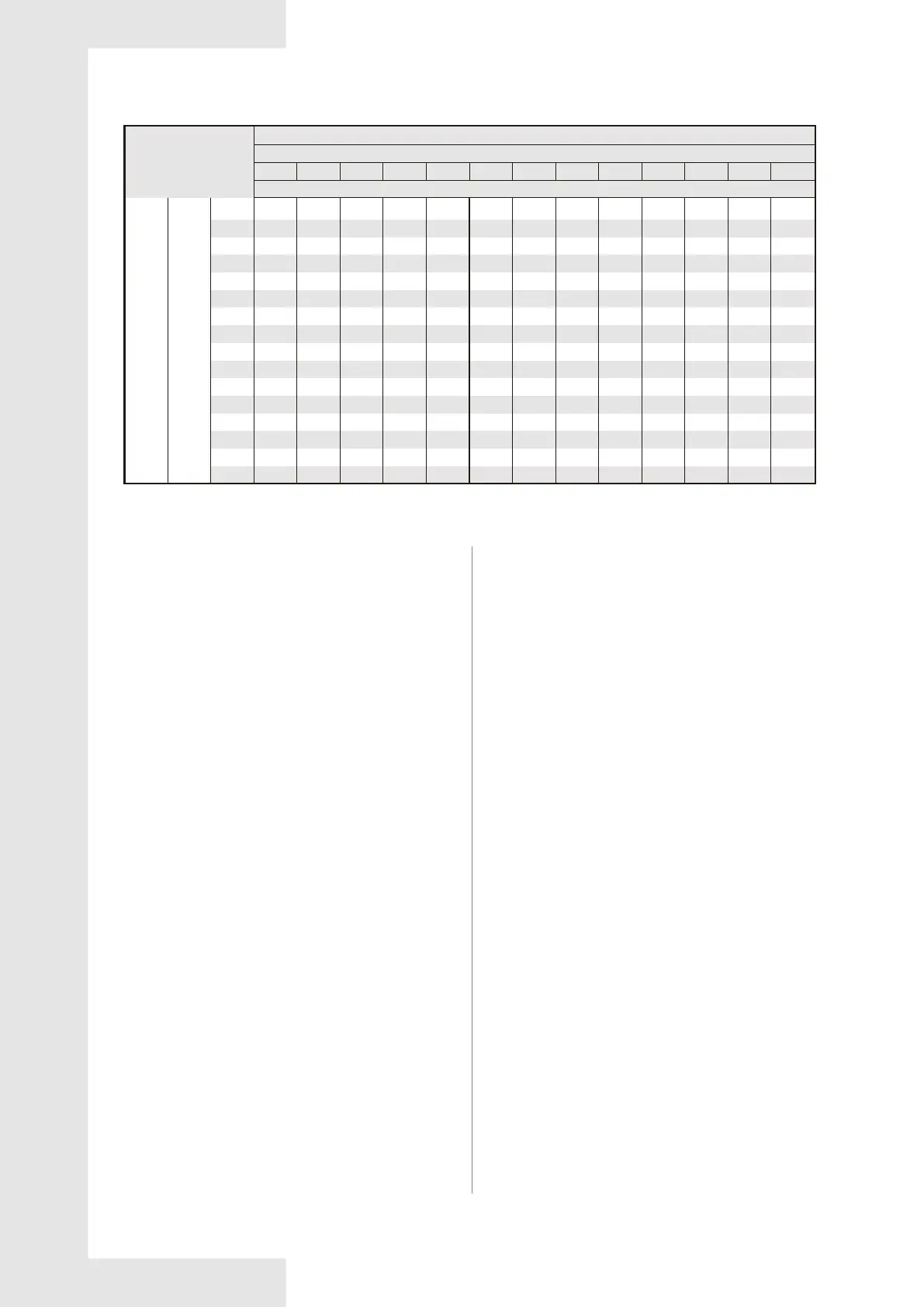
Table 7-15 Refrigerant charge for H/P system
135
128
121
114
107
100
93
86
79
72
65
58
51
44
37
30
431
405
379
354
328
302
291
280
270
259
248
439
413
387
361
335
309
298
287
276
265
254
447
421
395
368
342
316
305
294
282
271
260
455
429
402
376
349
323
312
300
289
277
266
463
436
410
383
357
330
318
307
295
284
272
265
471
444
417
391
364
337
325
313
302
290
278
271
264
479
452
425
398
371
344
332
320
309
297
285
278
271
264
487
460
433
405
378
351
339
327
316
304
292
285
278
271
264
495
468
440
413
385
358
346
334
323
311
299
292
285
278
271
503
475
448
420
393
365
353
341
330
318
306
299
292
285
278
511
483
455
428
400
372
360
348
337
325
313
306
299
292
285
518
490
462
435
407
379
367
355
344
332
320
313
306
299
292
Heating Charge Chart/Tableau De Charge de Chauffage60
Heating Mode
Mode
De Chauffage
Indoor Dry Bulb Temperature(oF)/Temperature Interieur au Themometre sec(en oF)
Low Pressure Service Port(psig)
Vanne Détectée de Pression Basse(en psig)
High Pressure Service Port(psig)/Vanne Détecté de Pression Haute(en psig)
60 62 64 66 68 70 72 74 76 78 80 82
8.1 Compressor Crankcase Heater
(Optional)
8.2 Protection
8.3 Defrost Mode Introduction
(Heat Pump Only)
8.2.1 Protection for HP system
8 SYSTEM OPERATION
Refrigerant migration during the off cycle can result in a
noisy start up. Add a crankcase heater to minimize
refrigeration migration, and to help eliminate any start up
noise or bearing “wash out”.
All heaters are located on the lower half of the
compressor shell. Its purpose is to drive refrigerant from
the compressor shell during long off cycles, thus
preventing damage to the compressor during start-up.
At initial start-up or after extended shutdown periods,
make sure the heater is energized for at least 12 hours
before the compressor is started. (Disconnect switch on
and wall thermostat off.)
The crankcase heater will start up or shut down
according to the following logic:
The crankcase heater will start up when the compressor
is off and T4<41°F.
The crankcase heater will shut down when T4 ≥ 45 °F
In any condition, the crankcase heater will shut down
when the compressor is on
If sensors(T3&T4) become open-circuit or short-circuit,
the compressor ,outdoor fan motor and reversing valve
circuit will shut down.
Discharge temperature protection:
If discharge temp. is > 239°F, the compressor will shut
down, If discharge temp. is < 167°F, the compressor will
resume operation.
High pressure protection
If high pressure is >609PSIG,the compressor and the
outdoor fan motor will stop running.
If high pressure is <464PSIG,the compressor and the
outdoor fan motor will resume running(3 minutes delay
necessary ).
Low pressure protection
When low pressure is <21PSIG,the compressor and
the outdoor fan motor will stop running.
When low pressure is >44PSIG,the compressor and
the outdoor fan motor will resume running(3 minutes
delay necessary ).
In stand-by status, if low pressure protection was
detected, the compressor will not start.
If protection cycles occur four times within 30 minutes,
the compressor and outdoor fan will shut down. In this
condition, the system needs to power on once more in
order to keep on working.
T4 function:
When T4 is < 5 °F, the compressor will stop. If the
electrical heater kit is installed in the indoor unit, the
outdoor unit will send the operation signal to the indoor
unit.
When T4 is > 10.4 °F, the compressor will restart .
Manual defrost mode
To manually cycle the defrost mode, set switch SW3-1
to the “ON” position (See Fig 8-1). The system will
engage a defrost cycle, and automatically exit defrost
mode once the Shut-down conditions of defrost mode
described below are met.
Caution: Once the manual defrost mode is finished,
please set switch SW3-1 back to “OFF”.
20
 Loading...