18-BC59D1-1 3
Installer’s Guide
BRAZING REFRIGERANT LINES
1. Remove lower access cover to access service valves.
2. Before brazing, remove plugs from external copper stub
tubes. Clean internal and external surfaces of stub tubes
prior to brazing.
3. Cut and fit tubing, minimizing the use of sharp 90° bends.
4. Insulate the entire gas line and its fittings.
5. Do NOT allow uninsulated liquid line to come in direct
contact with bare gas line.
6. Precautions should be taken to avoid heat damage
to the pressure tap valve core during brazing. It is
recommended that the pressure tap port valve
core be removed and a wet rag wrapped around
the valve body.
NOTE:
Use care to make sure that no moisture enters pressure tap
port, while wet rag is being used.
NOTE:
Precautions should be taken to avoid heat damage to
basepan during brazing. It is recommended to keep the
flame directly off of the basepan.
7. Use a Dry Nitrogen Purge and Brazing Alloy without
flux when brazing the field line to the copper factory
connection. Flow dry nitrogen into either valve pressure
tap port, thru the tubing and out the other port while
brazing.
8. Braze using accepted good brazing techniques.
LEAK CHECK
IMPORTANT:
Replace pressure tap port valve core before attaching hoses for
evacuation.
After the brazing operation of refrigerant lines to both the
outdoor and indoor unit is completed, the field brazed
connections must be checked for leaks. Pressurize through
the service valve ports, the indoor unit and field refrigerant
lines with dry nitrogen to 350-400 psi. Use soap bubbles or
other leak-checking methods to see that all field joints are
leak-free! If not, release pressure; then repair!
SYSTEM EVACUATION
NOTE:
Since the outdoor unit has a refrigerant charge, the gas and
liquid line valves must remain closed.
1. Upon completion of leak check, evacuate the refrigerant
lines and indoor coil before opening the gas and liquid
line valves.
2. Attach appropriate hoses from manifold gauge to gas
and liquid line pressure taps.
NOTE:
Unnecessary switching of hoses can be avoided and com-
plete evacuation of all lines leading to sealed system can be
accomplished with manifold center hose and connecting
branch hose to a cylinder of HCFC-22 and vacuum pump.
3. Attach center hose of manifold gauges to vacuum pump.
4. Evacuate until the micron gauge reads no higher than
350 microns.
5. Close off valve to vacuum pump and observe the micron
gauge. If gauge pressure rises above 500 microns in
one (1) minute, then evacuation is incomplete or system
has a leak.
6. If vacuum gauge does not rise above 500 microns in
one (1) minute, the evacuation should be complete.
7. With vacuum pump and micron gauge blanked off,
open valve on HCFC-22 cylinder and charge refriger-
ant lines and indoor coil with vapor to tank pressure
of HCFC-22 supply.
NOTE:
DO NOT VENT REFRIGERANT INTO THE ATMOSPHERE.
8. Close valve on HCFC-22 supply cylinder. Close valves on
manifold gauge set and remove refrigerant charging
hoses from liquid and gas pressure tap ports.
NOTE:
A 3/16" Allen wrench is required to open liquid line service
valve. A 1/4" Open End or Adjustable wrench is required to
open gas line valve. A 3/4" Open End wrench is required to
take off the valve stem cap.
9. The liquid line shut-off valve can now be opened. Remove
shut-off valve cap. Fully insert hex wrench into the stem
and backout counterclockwise until valve stem just
touches rolled edge (approximately five [5] turns)
observing WARNING statement on page 3. See Figure 3.
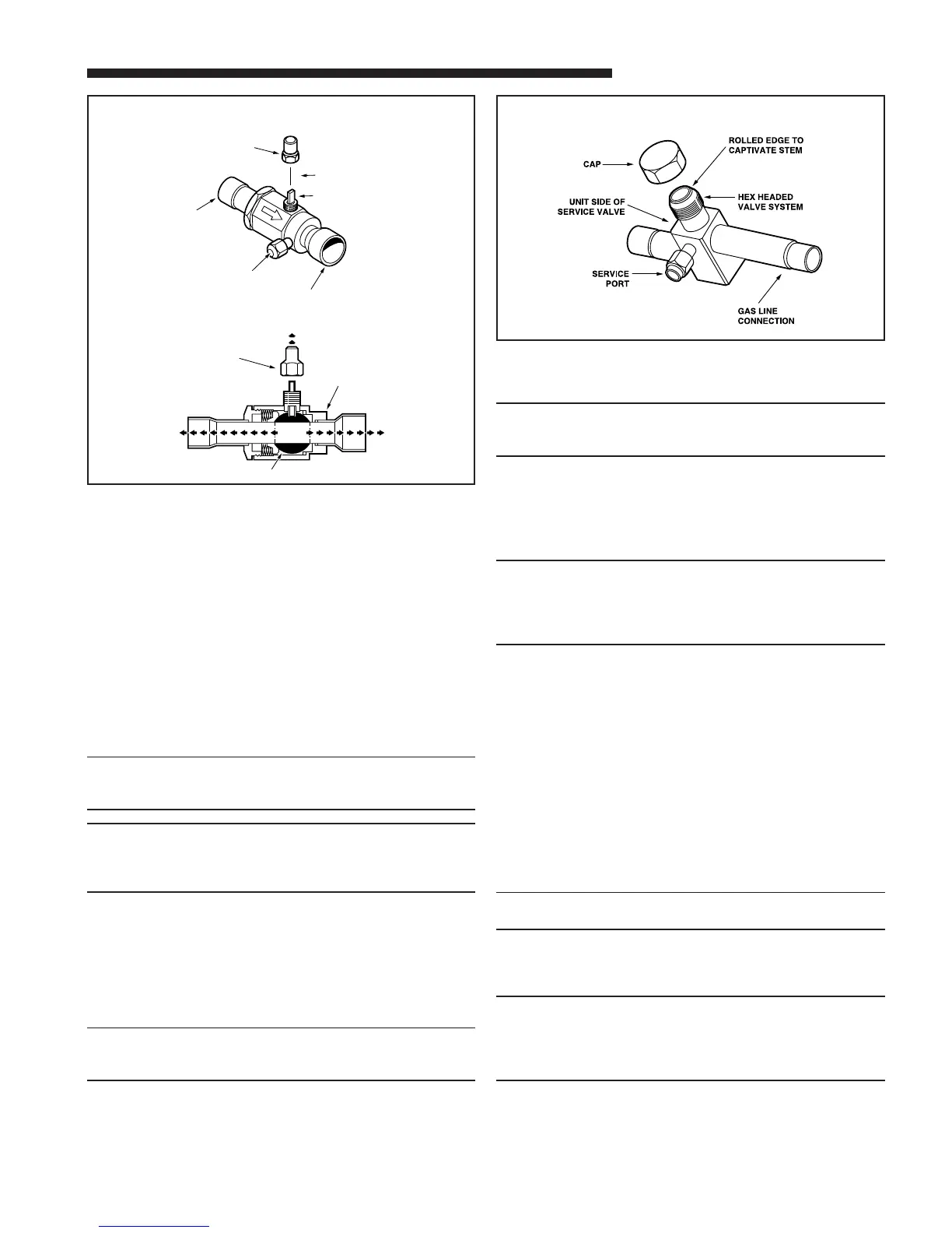
GAS LINE BALL SERVICE VALVE
4
CAP
1/4 TURN ONLY
COUNTERCLOCKWISE
FOR FULL OPEN
POSITION
VALVE STEM
GAS LINE CONNECTION
UNIT SIDE
OF VALVE
CAP
BODY
COOLING
CORE
PRESSURE TAP PORT
HEATING
GAS LINE SERVICE VALVE
5